Categories: Featured Articles » Electrician Secrets
Number of views: 238296
Comments on the article: 19
Welding wire connection
 In addition to those described earlier wire connection methods (see article Wiring methods: from twists to soldering), welding has been widely used recently.
Welding is preferable to all others: it is easiest to get a reliable and high-quality contact with it. Therefore, the uptime of the wiring is very long.
Now the wiring is most often performed by a copper wire, they try not to use an aluminum wire. Therefore, further we will focus mainly on the welding of copper wires.
Welding of copper wires can be done either by alternating or direct current at a voltage of 12 - 36V, while it should be possible to control the welding current. The most suitable for welding wires should be considered an inverter type welding machine.
Inverter Type Welding Machines
The advantages of inverter devices are widely known. First of all, it is small in size and weight, and some models have a strap for carrying over the shoulder. This allows you to hang the device on a belt over your shoulder and climb the step ladder to weld twists in a soldering box.
Welding invertersAs a rule, they have a wide range of regulation of welding current. The arc of such devices is very stable, it ignites well at low welding currents, so even an inexperienced welder can very soon achieve excellent results, get good quality welded joints.
Also, the advantages of inverter devices include low power consumption compared to conventional transformer welders. Therefore, it is quite possible to connect to household wiring: there will be no blinking of lights and failures in the operation of various household equipment, there will be no complaints from neighbors.
Welding copper wires is just as dangerous as conventional steel welding. The danger of "picking up bunnies" and getting burns from molten metal is fully preserved. Therefore, work on welding wires should be carried out in a welding mask, welding gloves. Overalls should also include work with welding. In addition, it is necessary to comply with all fire safety measures and safety regulations, as in conventional welding.
For welding copper wires, special carbon copper electrodes, which are often called “pencils,” are used. In the absence of such special electrodes, you can use a conventional carbon rod from an unusable battery. In this case, the welding current, depending on the diameter and number of wires to be welded, can be recommended, at least roughly, within the limits as indicated below.
A welding current of 70A is sufficient for welding two copper wires with a cross section of 1.5 mm2, 80 - 90A will be required for three of the same wires. For two or three wires with a cross section of 2.5 mm2, the current reaches 80-100A, and for three or four 100-120A.
These figures should be considered indicative, since the copper used in the wires, depending on the manufacturer, varies greatly in composition and properties. Accordingly, the welding modes will also differ.
The optimal mode is when the electrode does not stick to the weld point and the arc is stable. This combination is achieved already in the process of work empirically. Approximately such limits should be followed when purchasing an inverter welding machine. If the device is supposed to be used only for such work, then a more powerful one is not required.
Welding technology wires
Actually welding consists of several technological operations. First, remove the sheath and insulation from the wires, and then to twist. Trim the resulting twist so that the ends of all the wires are at the same level, and the twist length would be at least 50 mm.
After that, a copper heat-removing clip is installed on the twist, and the "mass" of the welding machine is connected. After these operations, the end of the coal “pencil” charged into the holder is brought to the end of the twist and welding is performed. As a result, a neat ball of molten copper should form at the end of the twist, after which welding should be stopped. In order not to melt the insulation of the wires, the welding time of each twist should not exceed 1 - 2 seconds. After the welded coils have cooled, they should be insulated with an insulating tape or, more modern, using heat shrink tubing.
Homemade wire welding machines
Inverter apparatus for twisting coils are very good, but they have one drawback, perhaps the only one. This is a high price. Therefore, the acquisition of such an apparatus becomes appropriate when welding is performed regularly, and not from case to case, for example, in the conditions of specialized electrical engineering brigades and enterprises. If you just plan wiring replacement in a two or three room apartment on their own, it is quite possible to get by with a home-made welding machine, even just a transformer, of suitable power.
As such a transformer, the TBS series transformer (Armored Machine Transformer Transformer) shown in the figure is quite suitable 1.
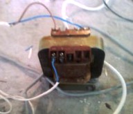
Picture 1. TBS series transformer
For welding wires, a transformer with a power of at least 600 W and a secondary winding voltage of 9 - 36V is quite suitable. An electrode holder and a clamp for connecting the “mass” are connected to the secondary winding.
Welding is carried out with a carbon electrode (rod from the battery) in the same way as it was written above for the inverter welding machine. Actually the whole process is the same: from stripping wires to touching the twist with a carbon rod and the subsequent insulation of the twists.
In the absence of such a transformer, it is easy to make it yourself. This will require a W - shaped transformer iron with a core area of at least 30 cm2. With an area of 30 cm2 and a mains voltage of 220 V, the primary winding contains 293 turns made by a winding wire with a diameter of 0.8 - 1.0 mm.
The secondary winding is wound in three wires with a diameter of 3 mm, or thinner in four to five wires, but only so that the total area is not less than 15 - 20 mm2. When the voltage of the secondary winding is 10V, it must contain 13 turns with the indicated iron.
If there is no such iron, then the number of turns can be determined by the formulas below.
W1 = 40 * U1 / S
W2 = 40 * U2 / S
According to these formulas, the number of turns for the primary and secondary windings is determined, where S is the core area, 40 is the empirical coefficient (it can lie in the range of 40-60, the better the iron, the smaller the number), U1 mains voltage (220V), U2 - required secondary voltage. By the way, this formula is suitable for calculating any transformer, not necessarily welding.
As in the previous case, you will need a welding mask or glasses and mittens, otherwise burns with molten metal or "bunnies" in the eyes are guaranteed. To simplify the welding process, you can use the special clamp shown in the figure. 2.
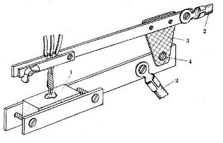
Picture 2. Twist welder
The design of the device is simple and understandable from the figure. The voltage from the welding transformer using wires 2 is supplied to the upper (movable arm) and lower (base) parts interconnected by an insulating plate 3, by means of a hinge 4. A carbon electrode 1 with a recess for the flux is used as a base, which is used as an ordinary borax sold in pharmacies.
Wires 2 should be as short as possible, and the cross section should be as maximum as possible, not less than the cross section of the secondary winding of the transformer.The power switch should be as close as possible, it is better if it is a passage switch on the wire, like a floor lamp.
The welding process in this case looks like this. First, the welded twist is fixed with a wing clamp on the movable arm. A flux is poured into the recess of the carbon electrode, the levers are compressed by hand. After that, voltage is applied to the welding transformer, and a ball forms in the recess of the carbon electrode under the flux layer. After that, the transformer should be turned off and wait a while until the ball cools directly in the fixture.
Welding time, as a rule, is practically determined, therefore, you should first practice on unnecessary scraps of wires. Using this device, welding of aluminum wires, as well as aluminum and copper, is possible. The methods for performing twists for this case are shown in the figure. 3.
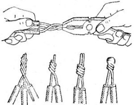
Picture 3. Twists for welding wires
Read about spot welding machineshere. The article describes several home-made designs of such devices for the home workshop.
Boris Aladyshkin
See also at e.imadeself.com
: