Categories: Featured Articles » Practical Electronics
Number of views: 407784
Comments on the article: 11
Spot welding in the home workshop
 Varieties and classification of welding
Welding is the process of obtaining an integral connection of parts due to the formation of interatomic bonds in the weld. Such bonds arise under the influence of local or general heating of the parts to be welded, or under the influence of plastic deformation, or both.
Welding is most often used for joining metals and their alloys, for joining thermoplastics, and even in medicine. But welding live tissue is beyond the scope of this article. Therefore, briefly consider only those types of welding that are used in technology.
The modern development of welding technology is such that it allows welding to be performed not only in production conditions, but also in the open air and even under water. In recent years, welding as an experiment has already been carried out in space.
For the production of welding, various types of energy are used. First of all, it is an electric arc or a flame of a gas burner. More exotic sources are ultrasound, laser radiation, an electron beam, and also friction welding.
All welding operations are associated with high fire hazard, gas contamination by harmful gases, ultraviolet radiation, and simply the risk of electric shock. Therefore, carrying out welding works requires strict observance of safety regulations.
All welding methods, depending on the type of energy and the technology of its use, are divided into three main classes: thermal class, thermomechanical class, and mechanical class.
Thermal class welding is carried out by melting due to the use of thermal energy. It’s mostly widely known arc welding and gas welding. Thermomechanical class welding is performed using thermal energy and mechanical pressure. For mechanical class welding, the energy of pressure and friction is used. All splits of welding into classes are made in accordance with GOST 19521-74.
Spot welding
Spot welding refers to the category of so-called contact welding. In addition to it, butt and seam welding also belong there. In the conditions of a home workshop, the last two types are practically impossible to implement, since the equipment is too complicated to repeat in artisanal conditions. Therefore, further only spot welding.
According to the above classification, spot welding belongs to the thermomechanical class. The welding process consists of several stages. First, the parts to be welded, previously combined in the desired position, are placed between the electrodes of the welding machine and pressed against each other. Then they are heated to a state of plasticity, and subsequent joint plastic deformation. When using automatic equipment in industrial conditions, a welding frequency of 600 dots per minute is achieved.
Brief spot welding technology
The parts are heated by supplying a short-term pulse of the welding current. The pulse duration varies between 0.01 ... 0.1 sec depending on the welding conditions. This short-term pulse ensures the melting of the metal in the zone of the electrodes and the formation of a common liquid core for both parts. After the current pulse has been removed, the components are held under pressure for some time to cool and crystallize the molten core.
The pressing of the parts at the time of the welding pulse provides the formation around the molten core of the sealing strip, which prevents the splash of the melt from the welding zone. Therefore, additional measures to protect the weld point are not required.
The compression force of the electrodes should be removed with a certain delay after the end of the welding pulse, which provides conditions for better crystallization of the molten metal. In some cases, at the final stage, it is recommended to increase the clamping force of the parts, which ensures forging of the metal and elimination of inhomogeneities inside the weld.
It should be noted that in order to obtain a high-quality weld, the surfaces to be welded must be pre-prepared, in particular, cleaned from thick oxide films or simply rust. For welding thin sheets are sufficient, up to 1 ... 1.5 mm, the so-called capacitor welding.
Capacitors charge continuouslysufficiently small current, consuming negligible power. At the time of welding, the capacitors are discharged through the parts to be welded, providing the necessary welding mode.
Such sources are used for welding miniature and subminiature parts in instrument making, electronic and radio engineering industries. In this case, welding of both ferrous and non-ferrous metals is possible, and even in various combinations.
Advantages and disadvantages of spot welding
Like everything in the world, spot welding has its advantages and disadvantages. First of all, the advantages include high profitability, mechanical strength of spot welds and the ability to automate welding processes. The disadvantage is the lack of tightness of the welds.
Home-made designs of spot welding machines
In the conditions of a home workshop, spot welding may just be necessary, so many devices have been developed that are suitable for self-production at home. A brief description of some of them will be given below.
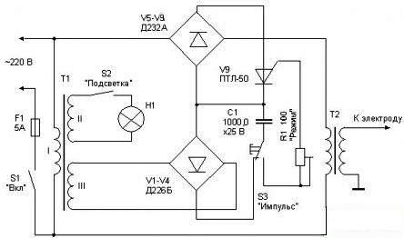
One of the first designs of the apparatus for spot welding was described in the journal RADIO N 12, 1978 p. 47-48. The circuit diagram of the apparatus is shown in Figure 1.
Figure 1. Schematic of the spot welding machine
Such a device does not differ in increased power, with its help it is possible to weld sheet metal up to 0.2 mm thick or steel wire with a diameter up to 0.3 mm. With these parameters, welding is quite possible thermocoupleas well as welding thin foil parts to massive steel substrates.
One of the possible applications is the welding of thin sheets of foil with pre-glued strain gauges to the tested parts. Due to the fact that the parts to be welded are small, the clamping force during welding is small, therefore, the welding electrode is made in the form of a gun. Clamping parts is carried out by hand.
The circuit of the welding machine is quite simple. Its main purpose is to create a welding pulse of the required duration, which provides various welding modes.
The main unit of the device is a welding transformer T2. A welding electrode is connected to its secondary winding (according to the upper end scheme) using a multicore flexible cable, and a more massive welded part is connected to the lower end. Connection should be reliable enough.
The welding transformer is connected to the network through the rectifier bridge V5 ... V8. A thyristor V9 is included in another diagonal of this bridge; when it is opened, the mains voltage through the rectifier bridge is applied to the primary winding of transformer T2. The thyristor is controlled using the S3 “Impulse” button located in the handle of the welding gun.
When connected to the network from an auxiliary source, capacitor C1 is immediately charged. The auxiliary source consists of a transformer T1 and a rectifier bridge V1 ... V4. If we now press the S3 “Impulse” button, then the capacitor C1 through its closed contact and resistor R1 will be discharged through the section of the control electrode - the cathode of thyristor V9, which will lead to the opening of the latter.
The opened thyristor will close the diagonal of the bridge V5 ... V9 (direct current), which will lead to the inclusion of a welding transformer T1.The thyristor will be open until capacitor C1 is discharged. The discharge time of the capacitor, and therefore the pulse time of the welding current, can be controlled by a variable resistor R1.
In order to prepare the next welding pulse, the “Impulse” button must be briefly released so that the capacitor C1 is charged. The next pulse will be generated by pressing the button again: the whole process will be repeated, as described above.
As a transformer T1, any low-power (5 ... 10W) with an output voltage on the III winding of about 15V is suitable. Winding II is used for backlighting, its voltage is 5 ... 6V. With the ratings C1 and R1 indicated on the diagram, the maximum duration of the welding pulse is about 0.1 sec, which ensures a welding current of 300 ... 500 A, which is quite enough for welding the small-sized parts mentioned above.
The T2 transformer is made on Sh40 iron. The thickness of the set is 70 mm, the primary winding is wound with a PEV-2 wire 0.8 and contains 300 turns. The secondary winding is wound immediately in two wires and contains 10 turns. The wire of the secondary winding is stranded with a diameter of 4 mm. You can also use a tire with a cross section of at least 20 sq. Mm.
It is quite possible to replace the PTL-50 thyristor with KU202 with the letters K, L, M, N. Moreover, the capacitor C1 will have to be increased to 2000 μF. That's just the reliability of the device with such a replacement can be somewhat reduced.
More powerful spot welding machine
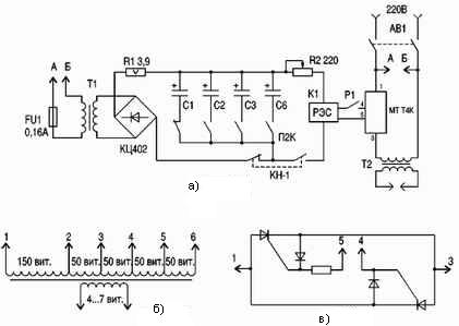
The apparatus described above can be called microwelding machine. A diagram of a more powerful apparatus is shown in Figure 2.
Figure 2. Schematic diagram of the spot welding machine
Upon closer examination, it is easy to notice that it is structurally very similar to the previous one and contains the same components, namely: a welding transformer, a semiconductor thyristor switch and a time delay device that provides the required welding pulse duration.
This scheme allows you to weld sheet metal up to 1 mm thick, as well as wire with a diameter of up to 4 mm. This increase in power compared to the previous circuit is achieved through the use of a more powerful welding transformer.
The general circuit of the apparatus is shown in Figure 2a. The primary winding of the welding transformer T2 is connected to the network through a thyristor proximity contactor type MTT4K. The direct current of such a starter is 80 A, the reverse voltage is 800 V. Its internal device is shown in Figure 2c.
The circuit of the module is quite simple and contains two thyristors, connected counter-parallel, two diodes and a resistor. Contacts 1 and 3 switch the load while contacts 4 and 5 are closed. In our case, they are closed using the contact group of relay K1. To protect against emergency situations, the circuit contains an AB1 circuit breaker.
Time relay assembled on transformer Tr1, diode bridge KTs402, electrolytic capacitors C1 ... C6, relay K1 and commutating switches and buttons. In the position shown in the diagram, when the machine AB1 is turned on, capacitors C1 ... C6 begin to charge.
Capacitors are connected to the diode bridge using a P2K switch with independent fixation, which allows you to connect a different number of capacitors and thereby control the time delay. The resistor R1 is installed in the capacitor charge circuit, its purpose is to limit the charging current of the capacitors at the initial moment of charging. This allows you to increase the life of the capacitors. Capacitors are charged through a normally closed contact on the KN1 button.
When the KN1 button is pressed, it closes normally - an open contact that connects the K1 relay to the timing capacitors. Normally - a closed contact at this time, of course, opens, which prevents the connection of relay K1 directly to the rectifier bridge.
The relay operates, closes the control contacts of the thyristor relay with its contacts, which turns on the welding transformer.After the capacitors are discharged, the relay will turn off, the welding pulse will stop. To prepare for the next pulse, the KN1 button must be released.
For accurate selection of the pulse time, a variable resistor R2 is used. As a relay, K1 is suitable reed relay type RES42, RES43 or the like with a response voltage of 15 ... 20 V. Moreover, the lower the relay actuation current, the longer the time delay. The current between contacts 4 and 5 of the thyristor starter does not exceed 100 mA, so any low-current relay is suitable.
Capacitors C1 and C2 at 47 μF, C3, C4 100 μF, C5 and C6 470 μF. The operating voltage of the capacitors is at least 50 V. Transformer Tr2 is suitable for anyone with a power of not more than 20 W with a secondary voltage of 20 ... 25 V. The rectifier bridge can be assembled from separate diodes, for example, the widespread 1N4007 or 1N5408.
The welding transformer is made on a magnetic circuit from a burnt LATRA of 2.5 A. After removing the old winding, the iron is wrapped in at least three layers of varnish. At the ends of the magnetic circuit, before winding the varnished cloth, rings of thin electrical cardboard are installed, which are bent along the outer and inner edges of the ring. This prevents the destruction of the lacquer fabric during winding and subsequent operation.
The primary winding is carried out with a wire with a diameter of 1.5 mm, it is best if the wire is with fabric insulation, which improves the conditions for impregnation of the winding with varnish. For impregnation, you can use KC521 varnish or the like. The number of turns is shown in Figure 2b. Using taps, you can make a rough adjustment of the welding current. Between the primary and secondary windings, a layer of cotton tape is wound, after which the coil is impregnated with varnish.
The secondary winding is made of stranded wire in silicone insulation with a diameter of 20 mm and contains 4 ... 7 turns. Wire area not less than 300 sq. Mm. At the ends of the wire, lugs are installed, which should be soldered for better contact. It is possible to carry out a secondary winding with a bundle of several thinner wires. The total area must be at least specified, and all wires must be wound at the same time. This design of the transformer provides a welding current of up to 1500 A. The open circuit voltage is 4 ... 7 V.
The welding - contact mechanism is performed in accordance with the nature of the work performed according to one of the known schemes. Most often these are welding pliers. The pressure created by the mechanism is about 20 KG / cm2. More precisely, this effort is selected in a practical way. Contacts are made of copper or beryllium bronze. At the same time, the size of the contact pads should be as small as possible, which ensures a better welding core.
Amateur designs for spot welding can now be found a lot. Everything comes into play. For example, one of the designs is based on TS270 power transformers from old tube color TVs. To create such an installation, six transformers were needed. Even microprocessor-controlled circuits appear, but the general meaning of the structures remains unchanged: to create a short-term pulse of the welding current and a sufficient clamping force at the welding site.
Boris Aladyshkin
See also at e.imadeself.com
:


