Categories: Practical Electronics, Electrician Secrets
Number of views: 303,358
Comments on the article: 25
How to make a simple current regulator for a welding transformer
 An important design feature of any welding machine is the ability to adjust the operating current. In industrial apparatuses, different methods of adjusting the current are used: shunting with various types of chokes, changing the magnetic flux due to the mobility of the windings or magnetic shunting, using active ballast resistances and rheostats. The disadvantages of this adjustment include the complexity of the design, the bulkiness of the resistances, their strong heating during operation, inconvenience when switching.
The most optimal option - even when winding the secondary winding, make it with taps and, by switching the number of turns, change the current. However, this method can be used to adjust the current, but not to adjust it over a wide range. In addition, the regulation of the current in the secondary circuit of the welding transformer is associated with certain problems.
So, significant currents pass through the control device, which leads to its cumbersomeness, and it is almost impossible to select such powerful standard switches for the secondary circuit that they can withstand currents up to 200 A. Another thing is the primary winding circuit, where the currents are five times less.
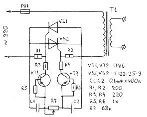
After a long search through trial and error, the optimal solution to the problem was found - the well-known thyristor regulator, the circuit of which is shown in Fig. 1.

With the utmost simplicity and accessibility of the element base, it is easy to manage, requires no settings, and has proven itself in work - it works just like a "clock".
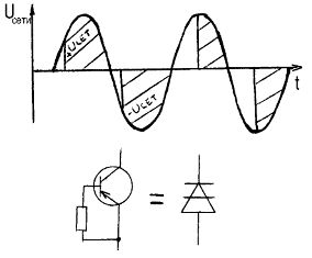
Power regulation occurs when the primary winding of the welding transformer is periodically disconnected for a fixed period of time at each half-period of the current. The average current value decreases.
The main elements of the regulator (thyristors) are turned on and parallel to each other. They are alternately opened by current pulses generated by transistors VT1, VT2. When the regulator is connected to the network, both thyristors are closed, the capacitors C1 and C2 begin to charge through the variable resistor R7. As soon as the voltage on one of the capacitors reaches the avalanche breakdown voltage of the transistor, the latter opens, and the discharge current of the capacitor connected to it flows through it.

Following the transistor, the corresponding thyristor opens, which connects the load to the network. After the start of the next alternating current half-cycle alternating current sign, the thyristor closes and a new cycle of charging capacitors begins, but in reverse polarity. Now the second transistor opens, and the second thyristor connects the load to the network again.
By changing the resistance of the variable resistor R7, it is possible to regulate the moment the thyristors are turned on from the beginning to the end of the half-cycle, which in turn leads to a change in the total current in the primary winding of the welding transformer T1. To increase or decrease the adjustment range, you can change the resistance of the variable resistor R7 up or down, respectively.
Transistors VT1, VT2 operating in the avalanche mode, and resistors R5, R6 included in their base circuits, can be replaced with dynistors. The anodes of the dinistors should be connected to the extreme terminals of the resistor R7, and the cathodes should be connected to the resistors R3 and R4. If the regulator is assembled on dinistors, then it is better to use devices such as KN102A.
As VT1, VT2, transistors of the old type P416, GT308 type have proven themselves well. It is quite realistic to replace them with more modern low-power high-frequency ones that have similar parameters.
Variable resistor type SP-2, the rest type MLT. Capacitors like MBM or MBT for a working voltage of at least 400 V.

A properly assembled regulator does not require adjustment. You just need to make sure stable operation of transistors in avalanche mode (or in the stable inclusion of dinistors).
Attention! The device has galvanic connection to the network. All elements, including thyristor heatsinks, must be isolated from the housing.
See also on the topic: Thyristor Power Regulators andHome-made spot welding machines for the home workshop
See also at e.imadeself.com
:
