Categories: Novice electricians, Electrician at home
Number of views: 504005
Comments on the article: 14
Connection diagram for circuit breaker, sockets and lamps
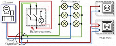
This figure shows simplified circuit diagram for connecting a switch, sockets and lamps. It is quite common and is widely used in the electrification of residential apartments, basements, garages, industrial, construction objects, etc. And now let's deal with this scheme in more detail.
For better understanding wiring diagram circuit breaker, sockets and lamps are drawn as it is usually located during its installation.
Let's start with the electrical panel. Each house and apartment must have a shield to which the input from the main power line (from the nearest power pole or from the main distribution panel on the site) is suitable. On (in) this shield, as a rule, are electric meter, RCD, circuit breakers, circuit breakers and additional devices (for example, voltage indicators, surge protection etc.). It is from him that the whole room (a private house, apartment) is powered.

Suppose we have a three-room apartment. Usually this is done: in each room, a junction box is installed (it is shown in the figure in a circle). The wires (cable) from the shield are brought to it and the power is taken from one of the machines on it. Such junction boxes are the switching points of all power wires of the electrical wiring (from switches, lamps, sockets, air conditioners, etc.) that are located in this room (room).
Now, as for the most circuit diagrams for switches and lamps. As you understand (looking at the picture), in the junction box there is a phase (red wire) and zero (blue), which come from the shield - Wire color phase, zero, ground. A phase wire is taken and a common wire (also red) connected to the two-key switch is connected to it.
In the open position of the switch, the phase simply sits on the common terminal and waits until it is pressed onto the wire by pressing the key (s) that is connected to one of the lamps. The wires going to the lamp (s) are marked in green. When the circuit breaker is open, these wires are de-energized. By the way, they also pass through the junction box.
 As you know, some types of switches have neon lights. In the figure, it is shown inside the switch in the form of a circle with two smaller circles. This neon bulb is connected via an additional resistance (in series). This backlight should be turned on as follows: one of its wires is screwed to the common terminal of this switch, and the second wire to one of the remaining terminals (on the switch).
This backlight will illuminate when the switch is in the open contact position. Yes, I want to remind you that such a backlight works well with incandescent bulbs. With economical lamps, it is undesirable to connect it (just the light will begin to flash even when the position is off).
Lamps, as a rule, have several lamps. When connecting the lamps separately (one part of the lamp is lit, the other and both at once) wire connection happens like this: from each of the lamps one wire is taken and connected into one twisting or terminal block. The second wires from these lamps are grouped in two (phase) twists. As a result, the first common twist is connected to the zero coming from the junction box, and the grouped remaining two twists sit on two wires (green) coming from the switch.
Now, with regard to the socket connection scheme. Everything is very simple here.Two wires are taken (phase and zero) coming from the junction box and connected to the contacts on the outlet itself.
Next, a second wire is drawn from the same outlet (in parallel) and connected to another. In parallel with a going wire, you should connect the sockets in the case when these sockets are located close to each other (forming a group of sockets).
Read more about how to connect the unit from the outlet and switches here: How to install a block of electrical switches with a socket
If the sockets are far away from each other (for example, on the opposite wall of the room), then they are powered from another wire (cable) coming from a common junction box belonging to this room.
When forming connecting groups of sockets, you should remember and take into account the total load on them (total current). Since by connecting too many outlets in one group and powering them from a common cable having a small cross-section, you can get current overload on this cable and eventually heat it up (fire).
Alexander Viryukhalov
Be sure to check out:
Schematic and wiring diagrams of lighting in an apartment and a house
Electrical wiring in a private house. Top articles
Selected materials on the topic "Lighting control in the house"
See also at e.imadeself.com
:
