Categories: Electrician at home, Electric installation work
Number of views: 73132
Comments on the article: 13
Schematic and wiring diagrams of lighting in an apartment and a house
 According to the new rules in force, all luminaires must be connected with three electric wires. In cases where the apartment is being repaired and the wiring is done according to a two-wire circuit, modernization and transition to a three-wire power supply system with a PE conductor should be carried out. But if the place for connecting it is not prepared on the floor board, then the ends of the protective zero with the yellow-green marking of the insulation are left ready for connection, but they do not commute.
Luminaire connection diagram via a single-button switch
The contact of the switch is connected from phase L. The second end of the cable core is output through the additional terminal of the DC in the junction box on the cartridge to the lighting lamp. The connection of the cartridge must be done so that when replacing a burned-out bulb with the switch on (this is not recommended, but quite often people go on violation), the person does not fall under the phase potential.
The figure shows that the outer shell of the lamp base is connected to working zero N, and the remote contact is connected to phase L.
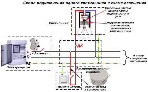
When installing the electrical wiring of lighting schemes, the rules of use must be observed color marking insulation for each highway. In the future, it will greatly facilitate troubleshooting and implementation of improvements. Each conductor L, N and PE throughout the apartment must be of the same color. It is customary to use conductors with yellow-green insulation for protective zero, blue for working N, and the remaining, for example, red or white, for phase L.
Such a circuit diagram is quite simple, but in the junction box of the RK there may be difficulties with connecting the wires to the terminals. The fact is that wires from four cables from housing shield, switch, lamp and trunk to the next lamp.
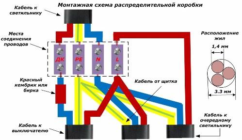
The wire going from the switch to the lighting device, refers to the phase. But in this cable, the red wire is already used for the phase. Therefore, you have to use one that has a blue color, but it should not be confused with a working zero. To do this, put on insulation cambric red or a tag with the inscription. This conductor is connected to an additional terminal of the DC, which, when the switch is turned on, is under phase potential.
Such a scheme is widespread, it is recommended to constantly repeat it for each lamp without changes. This will facilitate the possible work of troubleshooting the electrical circuit and making additional connections.
With this method, three wires can be connected into one hole at the terminal, but several features of their connection should be taken into account. If the conductor cross section for lighting is standard at 1.5mm2, then its diameter is 1.4 mm. For three such conductors, an internal hole diameter of not less than 3.3 mm is required, but better than 4. All three conductors must be passed under both mounting screws and tightened to create a reliable electrical contact.
If before inserting into the hole, perform a tight twisted veins, then the surface of their contact will increase, providing less contact resistance. This eliminates excessive heating of wires from heavy loads. If it is possible to weld the wires after twisting, then you should not refuse it.
This connection method is the most reliable. In this case, the block is used only for fixing the wires inside the junction box and you can only screw one fixing screw, but all the cores are inserted on one side.
Using welding, you can increase the number of switched conductors 1.5mm2 up to four in a hole with a diameter of 4 mm. If the terminal block is rigidly fixed inside the junction box, then the connecting ends can be pushed through the inner hole of the tube so that the welded ends of the cores protrude slightly in the form of welded balls. They are allowed not to isolate. This case is shown in the figure below.
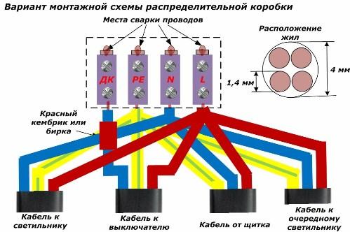
But it is best to hide and cover them with a layer of insulation for reliability.
Scheme of connecting fixtures through a two-gang switch
In chandeliers with several bulbs, lamps are usually divided into two groups. This allows you to create different room illumination using light from one or the other part of the circuit, or both together. Each group of bulbs has its own button on the on / off switch.
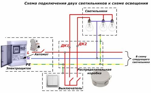
In this scheme, you will need four-wire wiring from the junction box to the switch and chandelier. The diagram shows that for switching wires in the RK, two additional terminals DK1 and DK2 will have to be used, through which the outgoing phase from the switch is fed to the remote contacts of the bulbs.
Here, too, phase L is brought to the switch so that both of its contacts are activated, and the zero from its wire is connected directly to all lampholders and is output to the bulb base.
The circuit for mounting the terminals in the junction box is similar to the one considered earlier, but another terminal is added to it - now there are five of them.
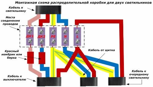
The maximum number of cores is suitable for one hole of the block - three. This allows the use of pads with an inner diameter of 3.3 mm.
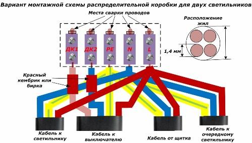
If you use welding to connect the cores, the number of cores inserted into one terminal will increase to four. For them, an internal hole diameter of 4 mm is required.
Luminaire connection diagram for corridor lighting
Here we consider the option of controlling the light source using two switches located at a considerable distance from each other. In this scheme, you can use ordinary two-key or special "pass-through" switches or switches with group contacts.
The light comes on or goes out with a certain combination of keys on both switches. There is no strict fixation of their position. But the lighting can be controlled from either end of the corridor.
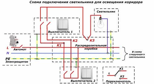
From the junction box with terminals K1 and K2 to each switch is a four-wire cable. The phase to the lamp is fed through terminal K3 from the RC after switching by switches.
The junction box wiring diagram consists of six terminals.
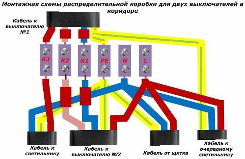
Here it is allowed to use terminals with an inner diameter of 3.3 mm because the maximum number of connected cores does not exceed three. But if you use conductor welding, then the installation will have to be done on one side and the number of terminals will increase to seven. Moreover, in some places the wires will have to be welded in four and use terminals with an internal diameter of 4 mm or more for them.
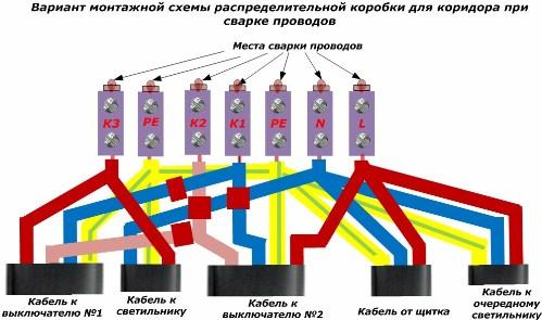
For switching the PE conductor, you need to use two terminals.
An increased number of terminals may require larger junction box dimensions.
Luminaire connection diagram for corridor lighting with pulse relay control
The design of the relay allows light to be switched by means of a pulsed supply of a phase potential to terminal S located on its housing. After the first pulse coming from pressing any button, the relay will connect phase L to terminal C, connected via terminal K3 to the remote contact of the lamp. At the second pulse, the relay removes voltage from its output terminal and the light goes out.
Buttons must be used with self-return from the springs. They can be located in places at a great distance. It’s quite convenient to turn on the light when entering the bedroom from the corridor, and turn off the button at the bedside table near the head of the bed.
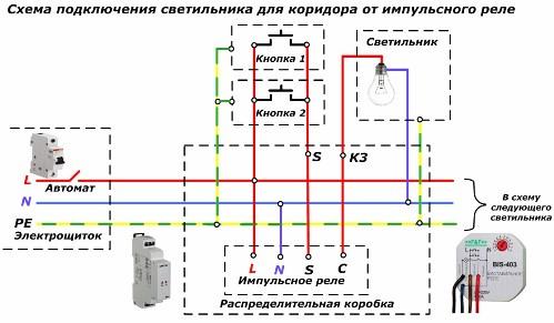
Impulse relays can be made with a different housing, which is designed for mounting on Din rail inside the dashboard or installation in a junction box.
Both light control buttons are connected in parallel. This facilitates the installation and preparation of highways for the cable, which should have three cores: two for operation and one for PE protection by the conductor.
When placing the relay inside the junction box, it is necessary to analyze the dimensions of all devices and provide convenient access to them for operation.
The wiring diagram for such lighting is shown in the figure. When using it, you can reduce the cross-sectional area of the wires connecting the terminals of the buttons, up to 0.35 mm2. They reliably withstand the load that occurs when a phase potential is applied to terminal S of the pulse relay.
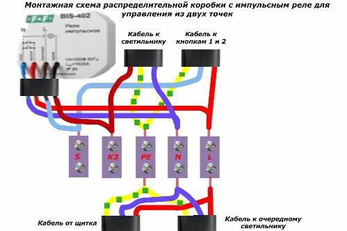
Sometimes it may be necessary to control the light from several places, for example, lighting the entrance to the house from the street and from rooms. To do this, just connect several buttons in parallel, as shown in the picture below.
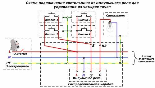
The wiring diagram for this case will be as follows.
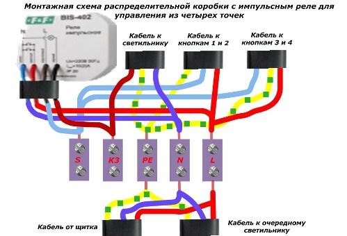
In this way, it is convenient to control the lighting from places located at a great distance from the light source and located in various rooms.
Download this article in PDF format here: https://e.imadeself.com/en/shemy1.zip
See also at e.imadeself.com
:
