Categories: Featured Articles » Practical Electronics
Number of views: 276,201
Comments on the article: 14
How to make a power supply from an electronic transformer
 After all that has been said in the previous article (see How is an electronic transformer arranged?), it seems that making a switching power supply from an electronic transformer is quite simple: put a rectifier bridge on the output, smoothing capacitor, if necessary, a voltage regulator and connect the load. However, this is not quite true.
The fact is that the converter does not start without load or the load is not sufficient: if you connect an LED to the rectifier output, of course, with a limiting resistor, you will be able to see only one flash of the LED when it is turned on.
To see another flash, you will need to turn off and on the converter to the network. In order for the flash to turn into a constant glow, you need to connect an additional load to the rectifier, which will simply select the useful power, turning it into heat. Therefore, such a scheme is used when the load is constant, for example, a DC motor or an electromagnet, which can only be controlled by the primary circuit.
If the load requires a voltage of more than 12V, which is produced by electronic transformers, it will be necessary to rewind the output transformer, although there is a less time-consuming option.
An option of manufacturing a switching power supply without disassembling an electronic transformer
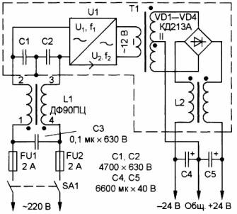
A diagram of such a power supply is shown in Figure 1.
Figure 1. Bipolar power supply for the amplifier
The power supply is made on the basis of an electronic transformer with a power of 105W. To manufacture such a power supply unit, it will be necessary to manufacture several additional elements: a line filter, a matching transformer T1, an output choke L2, rectifier bridge VD1-VD4.
The power supply has been operating for several years with a ULF power of 2x20W without complaints. With a rated mains voltage of 220V and a load current of 0.1A, the output voltage of the unit is 2x25V, and when the current is increased to 2A, the voltage drops to 2x20V, which is quite enough for the normal operation of the amplifier.
Matching transformer T1 is made on a ring K30x18x7 from ferrite grade M2000NM. The primary winding contains 10 turns of PEV-2 wire with a diameter of 0.8 mm, folded in half and twisted with a bundle. The secondary winding contains 2x22 turns with a midpoint, the same wire, also folded in half. To make the winding symmetrical, you should wind it in two wires at once - a bundle. After the winding, to obtain the midpoint, connect the beginning of one winding with the end of the other.
You will also have to make an L2 inductor yourself; to manufacture it, you need the same ferrite ring as for the T1 transformer. Both windings are wound with PEV-2 wire with a diameter of 0.8 mm and contain 10 turns.
The rectifier bridge is assembled on KD213 diodes, you can also use KD2997 or imported, it is only important that the diodes are designed for an operating frequency of at least 100 kHz. If instead of them you put, for example, KD242, then they will only warm up, and you won’t be able to get the required voltage from them. Diodes should be installed on a radiator with an area of at least 60 - 70cm2, using insulating mica pads.
Electrolytic capacitors C4, C5 are composed of three parallel-connected capacitors with a capacity of 2200 microfarads each. This is usually done in all switching power supplies in order to reduce the overall inductance of electrolytic capacitors. In addition, it is also useful in parallel to install ceramic capacitors with a capacity of 0.33 - 0.5 μF, which will smooth out high-frequency oscillations.
It is useful to install an input line filter at the input of the power supply, although it will work without it.As an input filter inductor, a ready-made DF50GTs inductor used in 3USTST TVs was used.
All units of the block are mounted on a board of insulating material by hinged mounting, using the findings of the parts for this. The entire structure should be placed in a shielding housing made of brass or sheet metal, with cooling holes provided in it.
A properly assembled power supply does not need adjustment, it starts working immediately. Although, before putting the block in the finished structure, you should check it. For this, a load is connected to the output of the unit - resistors with a resistance of 240 Ohms, with a power of at least 5 watts. Turning the unit on without load is not recommended.
Another way to refine the electronic transformer
There are situations that you want to use a similar switching power supply, but the load is very "harmful". The current consumption is either very small or varies widely, and the power supply does not start.
A similar situation arose when they tried in a lamp or chandelier with built-in electronic transformers, instead halogen lamps to put LED. The chandelier simply refused to work with them. What to do in this case, how to make it all work?
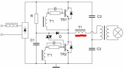
To deal with this issue, let's look at Figure 2, which shows a simplified diagram of an electronic transformer.
Figure 2. Simplified diagram of an electronic transformer
Pay attention to the winding of the control transformer T1, underlined by a red stripe. This winding provides current feedback: if there is no current through the load, or it is just small, then the transformer simply does not start. Some citizens who bought this device connect a 2.5W light bulb to it, and then carry it back to the store, they say, it does not work.
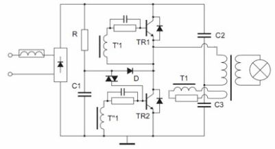
And yet, in a fairly simple way, you can not only make the device work almost without load, but also make it short-circuit proof. A method for such a refinement is shown in Figure 3.
Figure 3. Refinement of the electronic transformer. Simplified scheme.
In order for the electronic transformer to work without a load or with a minimum load, the current feedback should be replaced by voltage feedback. To do this, remove the current feedback winding (underlined in red in Figure 2), and instead solder the wire jumper into the board, naturally, in addition to the ferrite ring.
Further on the control transformer Tr1, this is the one that, on a small ring, wraps a winding of 2 - 3 turns. And there is one turn on the output transformer, and then the resulting additional windings are connected, as indicated in the diagram. If the converter does not start, then you need to change the phasing of one of the windings.
The resistor in the feedback circuit is selected within the range of 3-10Ohm, with a power of at least 1W. It determines the depth of feedback, which determines the current at which the generation will fail. Actually this is the fault current protection. The greater the resistance of this resistor, the lower the load current the generation will fail, i.e. operation of protection against short circuit.
Of all these improvements, this is perhaps the best. But this does not hurt to supplement it with another transformer as in the diagram according to Figure 1.
Boris Aladyshkin
See also at e.imadeself.com
:


