Categories: Featured Articles » Practical Electronics
Number of views: 149,726
Comments on the article: 13
How to determine unknown transformer parameters
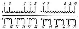
 The first thing to do is to take a piece of paper, a pencil and a multimeter. Using all this, ring the transformer windings and draw a diagram on paper. This should result in something very similar to Figure 1.
The conclusions of the windings in the picture should be numbered. It is possible that the conclusions will be much smaller, in the simplest case there are only four: two terminals of the primary (network) winding and two terminals of the secondary. But this does not always happen, more often there are several more windings.
Some conclusions, although they exist, may not “ring” with anything. Are these windings torn off? Not at all, most likely these are shielding windings located between other windings. These ends are usually connected to a common wire - the "ground" of the circuit.
Therefore, it is desirable to record the winding resistances on the obtained circuit, since the main goal of the study is to determine the network winding. Its resistance, as a rule, is greater than that of other windings, tens and hundreds of ohms. Moreover, the smaller the transformer, the greater the resistance of the primary winding: the small diameter of the wire and a large number of turns affect. The resistance of the lowering secondary windings is almost zero - a small number of turns and a thick wire.
About how to correctly measure the resistance with a multimeter, see here:How to measure voltage, current, resistance with a multimeter, check diodes and transistors

Fig. 1. Scheme of transformer windings (example)
Suppose that we managed to find the winding with the highest resistance, and we can consider it network. But you do not need to immediately include it in the network. In order to avoid explosions and other unpleasant consequences, it is best to make a test switch-on by turning on a series of coils with a winding, a 220V bulb with a power of 60 ... 100W, which will limit the current through the winding to 0.27 ... 0.45A.
The power of the bulb should approximately correspond to the overall power of the transformer. If the winding is determined correctly, then the bulb does not light, in extreme cases, the filament glows a little. In this case, you can almost safely include the winding into the network, for starters it is better to use a fuse for a current of no more than 1 ... 2A.
If the light bulb burns quite brightly, then it may turn out to be a winding of 110 ... 127V. In this case, you should ring the transformer again and find the second half of the winding. After that, connect the halves of the windings in series and re-enable. If the light goes out, then the windings are connected correctly. Otherwise, interchange the ends of one of the found half-windings.
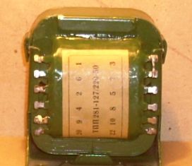
So, we assume that the primary winding is found, the transformer was able to be connected to the network. The next thing that needs to be done is to measure the idling current of the primary winding. For a working transformer, it amounts to no more than 10 ... 15% of the rated current under load. So for a transformer, the data of which are shown in Figure 2, when powered from a 220V network, the open-circuit current should be within 0.07 ... 0.1A, i.e. no more than a hundred milliamps.

Fig. 2. Transformer TPP-281
How to measure transformer idle current
Idling current should be measured with an alternating current ammeter. In this case, at the time of inclusion in the network, the terminals of the ammeter must be short-circuited, since the current when the transformer is turned on can be a hundred or more times the nominal. Otherwise, the ammeter may simply burn out. Next, open the conclusions of the ammeter and look at the result. In this test, let the transformer run for about 15 ... 30 minutes and make sure that no noticeable heating of the winding occurs.
The next step is to measure the voltage on the secondary windings without load, - the open circuit voltage.Suppose that a transformer has two secondary windings, and each voltage is 24V. Almost what you need for the above amplifier. Next, we check the load capacity of each winding.
For this, it is necessary to connect a load to each winding, in the ideal case a laboratory rheostat, and by changing its resistance, ensure that the voltage across the winding drops by 10-15 %%. This can be considered the optimal load for this winding.
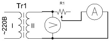
Together with voltage measurement, current is measured. If the indicated voltage drop occurs at a current, for example 1A, then this is the rated current for the tested winding. Measurements should be started by setting the rheostat engine R1 to the right position according to the diagram.

Figure 3. Test transformer secondary circuit
Instead of a rheostat, light bulbs or a piece of spiral from an electric stove can be used as a load. Measurements should be started with a long piece of spiral or with the connection of a single bulb. To increase the load, you can gradually shorten the spiral by touching it with a wire at different points, or by increasing the number of connected lamps one at a time.
To power the amplifier, one winding with a midpoint is required (see article "Transformers for UMZCH") We connect two secondary windings in series and measure the voltage. It should be 48V, the connection point of the windings will be the midpoint. If the voltage at the ends of the windings connected in series is equal to zero, then the ends of one of the windings should be interchanged.
In this example, everything turned out almost successfully. But more often it happens that the transformer has to be rewound, leaving only the primary winding, which is almost half the battle. How to calculate a transformer is the topic of another article, it was only told about how to determine the parameters of an unknown transformer.
Boris Aladyshkin
See also at e.imadeself.com
:
