Categories: Featured Articles » Practical Electronics
Number of views: 351,264
Comments on the article: 28
How to power a cordless screwdriver from an electrical network
 Cordless screwdriver is designed for screwing - unscrewing screws, screws, screws and bolts. It all depends on the use of interchangeable heads - bits. The scope of the screwdriver is also very wide: it is used by furniture assemblers, electricians, construction workers - finishers fasten gypsum boards with it and in general everything that can be assembled using a threaded connection.
This is a professional screwdriver application. In addition to professionals, this tool is also purchased exclusively for personal use during repair and construction work in an apartment or a country house, garage.

The cordless screwdriver is lightweight, small in size, does not require a network connection, which allows you to work with it in any conditions. But the whole trouble is that the battery capacity is small, and after 30 - 40 minutes of intensive work, you have to set battery for charging no less than 3 to 4 hours.
In addition, batteries tend to become unusable, especially when they do not use a screwdriver regularly: they hang a carpet, curtains, paintings and put it in a box. A year later, they decided to screw a plastic baseboard, and the screwdriver does not “pull”, Accumulator charging helps a little.
 A new battery is expensive, and not always on sale you can immediately find exactly what you need. In both cases, there is only one way out - to power the screwdriver from the mains through the power supply. Moreover, most often the work is carried out in two steps from the power outlet. The design of such a power supply will be described below.
In general, the design is simple, does not contain scarce parts, it can be repeated by anyone who is even a little familiar with electrical circuits and knows how to hold soldering iron. If you recall how many screwdrivers are in operation, then we can assume that the design will be popular and in demand.
The power supply must satisfy several requirements at once. Firstly, it is quite reliable, and secondly small-sized and lightweight and convenient for carrying and transporting. The third requirement, perhaps the most important thing, is the falling load characteristic, which allows avoiding damage to the screwdriver during overloads. Of no less importance is the simplicity of design and the availability of parts. All these requirements are fully met by the power supply, the design of which will be discussed below.
The basis of the device is a 60-watt Feron or Toshibra electronic transformer. Such transformers are sold in electrical goods stores and are designed to power halogen lamps with a voltage of 12 V. Typically, such lamps illuminate shop windows.
In this design, the transformer itself does not require any alterations, it is used as it is: two input network wires and two output wires with a voltage of 12 V. The circuit diagram of the power supply is quite simple and is shown in Figure 1.
Figure 1. Schematic diagram of the power supply
The transformer T1 creates a falling characteristic of the power supply due to the increased dissipation inductance, which is achieved by its design, which will be discussed above. In addition, the T1 transformer provides additional galvanic isolation from the network, which increases the overall electrical safety of the device, although this isolation is already in the electronic transformer U1 itself. By selecting the number of turns of the primary winding, it is possible, within certain limits, to control the output voltage of the unit as a whole, which allows it to be used with different types of screwdrivers.
The secondary winding of the transformer T1 is made with tap from the midpoint, which allows instead diode bridge apply a half-wave rectifier on just two diodes. Compared to the bridge circuit, the loss of such a rectifier due to the voltage drop across the diodes is two times lower. After all, there are two diodes, not four. In order to further reduce the power loss on the diodes in the rectifier, a diode assembly with Schottky diodes is used.
The low-frequency ripple of the rectified voltage smooths electrolytic capacitor C1. Electronic transformers operate at a high frequency, of the order of 40 - 50 KHz, therefore, in addition to ripples with the mains frequency, these high-frequency ripples are also present in the output voltage. Considering the fact that a half-wave rectifier increases the frequency by a factor of 2, these pulsations reach 100 or more kilohertz.
Oxide capacitors have a large internal inductance, so high-frequency pulsations cannot smooth out. Moreover, they will simply uselessly heat up the electrolytic capacitor, and may even render it unusable. To suppress these pulsations, a ceramic capacitor C2 is installed parallel to the oxide capacitor, of small capacity and with a small intrinsic inductance.
The operation indicator of the power supply can be monitored by the glow of the LED HL1, the current through which is limited by the resistor R1.
Separately, it should be said about the appointment of resistors R2 - R7. The fact is that electronic transformer Originally designed to power halogen lamps. It is assumed that these lamps are connected to the output winding of the electronic transformer even before it is connected to the network: otherwise it simply does not start without load.
If the electronic transformer is included in the network in the described design, then the subsequent pressing of the screwdriver button will not make it rotate. To prevent this from happening in the design and resistors R2 - R7 are provided. Their resistance is chosen so that the electronic transformer starts up confidently.
Parts and construction
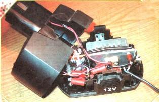
The power supply is located in the case of a regular battery that has expired, unless, of course, it has been thrown away yet. The basis of the design is an aluminum plate with a thickness of at least 3 mm, located in the middle of the battery case. The overall design is shown in Figure 2.
Figure 2. Power supply for a cordless screwdriver
All other parts are attached to this plate: an electronic transformer U1, a transformer T1 (on the one hand), and a diode assembly VD1 and all other parts, including the power button SB1, on the other. The plate also serves as a common output voltage wire, so the diode assembly is installed on it without laying, although for better cooling the heat sink surface of the VD1 assembly should be lubricated with heat transfer paste KPT-8.
The T1 transformer is made on a ferrite ring of size 28 * 16 * 9 from ferrite grade НМ2000. Such a ring is not deficient, widespread enough, problems with the acquisition should not arise. Before winding the transformer, first with a diamond file or just sandpaper, you should dull the outer and inner edges of the ring, and then insulate it with varnish cloth tape or FUM tape used for winding heating pipes.
As mentioned above, the transformer must have a large leakage inductance. This is achieved by the fact that the windings are located opposite each other, and not one under the other. The primary winding I contains 16 turns in two wires of the brand PEL or PEV-2. The wire diameter is 0.8 mm.
The secondary winding II is wound with a bundle of four wires, the number of turns 12, the diameter of the wire is the same as for the primary winding. To ensure the symmetry of the secondary winding, it should be wound in two wires at once, more precisely the harness. After winding, as is usually done, the beginning of one winding is connected to the end of the other. For this winding will have to "ring" the tester.
As the SB1 button, the MP3-1 microswitch is used, in which a normally closed contact is activated.A pusher is installed in the bottom of the power supply housing, which is connected to a button through a spring. The power supply is connected to a screwdriver, exactly the same as a regular battery.
If the screwdriver is now placed on a flat surface, the pusher presses the SB1 button through the spring and the power supply turns off. As soon as the screwdriver is picked up, the released button will turn on the power supply. It remains only to pull the trigger of the screwdriver and it will work.
A bit about the details
Details in the power supply are few. Capacitors it’s better to use imported ones, it’s now even easier than finding parts of domestic production. VD1 diode assembly of type SBL2040CT (rectified current 20 A, reverse voltage 40 V) can be replaced with SBL3040CT, in extreme cases, two domestic diodes KD2997. But the diodes indicated in the diagram are not a deficit, since they are used in computer power supplies, and buying them is not a problem.
The design of the transformer T1 was mentioned above. As an LED, HL1 is suitable for anyone that is at hand.
Setting up the device is simple and comes down to only unwinding the turns of the primary winding of the transformer T1 to achieve the desired output voltage. The rated supply voltage of screwdrivers, depending on the model, is 9, 12 and 19 V. Unwinding the turns from the transformer T1, it is necessary to achieve, respectively, 11, 14 and 20 V.
When writing this article, the diagram and illustrations from the journal RADIO No. 07 for 2011 were used. The article "Mains power supply for a screwdriver" K. Moroz.
See also at e.imadeself.com
:


