Categories: Practical Electronics, Sources of light, All about LEDs, How does it work
Number of views: 440310
Comments on the article: 52
How are LED lamps
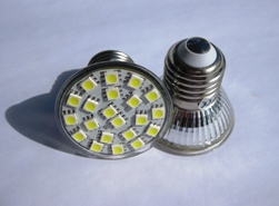 The article talks about the design of LED lamps. Several schemes of different complexity are considered and recommendations are given for the independent manufacture of LED light sources connected to a 220 V network.
Benefits of Energy Saving Lamps
The advantages of energy-saving lamps are widely known. First of all, it is actually low energy consumption, and in addition high reliability. Currently, the most widespread fluorescent lamps. Such a lamp power consumption 20 watts, gives the same illumination as a hundred-watt incandescent lamp. It is easy to calculate that energy savings are five times.
Recently, LED lamps are being mastered in production. The indicators of efficiency and durability are much higher than that of fluorescent lamps. In this case, electricity is consumed ten times less than incandescent lamps. The durability of LED lamps can reach 50 or more thousand hours.
New generation light sources, of course, are more expensive than simple incandescent lamps, but consume significantly less power and have increased durability. The last two indicators are designed to compensate for the high cost of new types of lamps.
Practical circuits of LED lamps
As a first example, we can consider the device of an LED lamp developed by the company "SEA Electronics" using specialized microcircuits. The electrical circuit of such a lamp is shown in Figure 1.
Figure 1. Scheme of the LED lamp of the company "SEA Electronics"
Ten years ago, LEDs could only be used as indicators: the light intensity was no more than 1.5 ... 2 microchandels. Super bright LEDs have now appeared, in which the radiation power reaches several tens of candelas.
When using high-power LEDs in conjunction with semiconductor converters, it became possible to create light sources that can withstand competition with incandescent lamps. A similar converter is shown in Figure 1. The circuit is quite simple and contains a small number of parts. This is achieved through the use of specialized microcircuits.
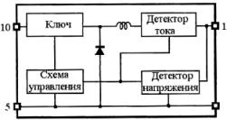
The first IC1 BP5041 chip is an AC / DC converter. Its structural diagram is shown in Figure 2.
Figure 2. Block diagram of BP5041.
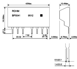
The microcircuit is made in the SIP type case shown in Figure 3.
Figure 3
A converter connected to a 220V lighting network provides a 5V output voltage at a current of about 100 milliamps. Connection to the network is through a rectifier made on the diode D1 (in principle, it is possible to use a bridge circuit of the rectifier) and a capacitor C3. Resistor R1 and capacitor C2 eliminate impulse noise. See also - How to connect a LED lamp to a 220 V network.
The entire device is protected by an F1 fuse, the rating of which must not exceed that indicated on the diagram. Capacitor C3 is designed to smooth the ripple of the output voltage of the converter. It should be noted that the output voltage does not have galvanic isolation from the network, which is completely unnecessary in this circuit, but requires special care and observance of safety rules during manufacture and commissioning.
Capacitors C3 and C2 must be at least 450 V operating voltage. Capacitor C2 must be film or ceramic. Resistor R1 can have a resistance in the range of 10 ... 20 Ohms, which is enough for normal operation of the converter.
The use of this converter eliminates the need for a step-down transformer, which significantly reduces the overall dimensions of the device.
A distinctive feature of the BP5041 chip is the presence of a built-in inductor as shown in Figure 2, which reduces the number of attachments and the overall size of the circuit board.
As a diode D1, any diode with a reverse voltage of at least 800 V and a rectified current of at least 500 mA is suitable. The widespread import diode 1N4007 fully satisfies such conditions. a varistor VAR1 of type FNR-10K391 is installed at the input of the rectifier. Its purpose is to protect the entire device from impulse noise and static electricity.
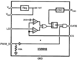
The second IC chip, type HV9910, is a PWM current stabilizer for super-bright LEDs. Using an external MOSFET transistor, the current can be set in the range from a few milliamps to 1A. This current is set by the resistor R3 in the feedback circuit. The chip is available in SO-8 (LG) and SO-16 (NG). Its appearance is shown in Figure 4, and in Figure 5 a block diagram.

Figure 4. Chip HV9910.
Figure 5. Block diagram of the HV9910 chip.
Using resistor R2, the frequency of the internal oscillator can be varied in the range of 20 ... 120 KHz. With the resistance of the resistor R2 indicated in the diagram, it will be about 50 KHz.
The inductor L1 is designed to store energy while the transistor VT1 is open. When the transistor closes, the energy stored in the inductor is transmitted through the high-speed Schottky diode D2 to the LEDs D3 ... D6.
Here is the time to recall the self-induction and Lenz rule. According to this rule, the induction current always has such a direction that its magnetic flux compensates for changes in the external magnetic flux, which (change) caused this current. Therefore, the direction of the EMF of self-induction has a direction opposite to the direction of the EMF of the power source. That is why the LEDs are turned on in the opposite direction with respect to the supply voltage (pin 1 of IC2, indicated on the diagram as VIN). Thus, the LEDs emit light due to the EMF of the self-induction coil L1.
In this design, 4 superbright LEDs of the TWW9600 type are used, although it is quite possible to use other types of LEDs manufactured by other companies.
To control the brightness of the LEDs in the chip has an input PWM_D, PWM - modulation from an external generator. In this scheme, such a function is not used.
If you are making such an LED lamp yourself, you should use a housing with a screw base of size E27 from an unusable energy-saving lamp with a power of at least 20 watts. The appearance of the structure is shown in Figure 6.
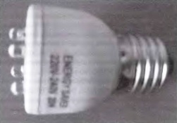
Figure 6. Homemade LED lamp.
Although the described scheme is quite simple, it is not always possible to recommend it for self-production: either you will not be able to buy the parts indicated on the scheme, or insufficient qualification of the assembler. Some may just be scared: “What if I won’t succeed?”. For such situations, you can offer several more simpler options both in circuitry and in the acquisition of parts.
Simple LED home lamp
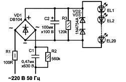
A simpler diagram of the LED lamp is shown in Figure 7.
Figure 7
This diagram shows that a bridge rectifier with capacitive ballast is used to power the LEDs, which limits the output current. Such power supplies are economical and simple, not afraid of short circuits, their output current is limited by the capacitance of the capacitor. Such rectifiers are often called current stabilizers.
The role of capacitive ballast in the circuit is performed by capacitor C1. With a capacitance of 0.47 μF, the operating voltage of the capacitor must be at least 630 V. Its capacity is designed so that the current through the LEDs is about 20 mA, which is the optimal value for LEDs.
The ripple of the bridge rectified voltage is smoothed by the electrolytic capacitor C2. To limit the charging current at the time of switching on, a resistor R1 is used, which also serves as a fuse in emergency situations.Resistors R2 and R3 are designed to discharge capacitors C1 and C2 after disconnecting the device from the network.
To reduce the dimensions, the operating voltage of the capacitor C2 was selected to be only 100 V. In case of breakdown (burnout) of at least one of the LEDs, the capacitor C2 will be charged to a voltage of 310 V, which will inevitably lead to its explosion. To protect against this situation, this capacitor is shunted by the zener diodes VD2, VD3. Their stabilization voltage can be determined as follows.
At a rated current through the LED of 20 mA, a voltage drop is created on it, depending on the type, within 3.2 ... 3.8 V. (A similar property in some cases allows the use of LEDs as zener diodes). Therefore, it is easy to calculate that if 20 LEDs are used in the circuit, then the voltage drop across them will be 65 ... 75 V. It is at this level that the voltage across the capacitor C2 will be limited.
Zener diodes should be selected so that the total stabilization voltage is slightly higher than the voltage drop across the LEDs. In this case, during normal operation, the zener diodes will be closed and will not affect the operation of the circuit. The 1N4754A zener diodes indicated on the circuit have a stabilization voltage of 39 V, and connected in series - 78 V.
If at least one of the LEDs breaks, the zener diodes will open and the voltage on the capacitor C2 will be stabilized at 78 V, which is clearly lower than the operating voltage of the capacitor C2, so there will be no explosion.
The design of a home-made LED lamp is shown in Figure 8. As can be seen from the figure, it is assembled in a housing from an unusable energy-saving lamp with an E-27 base.
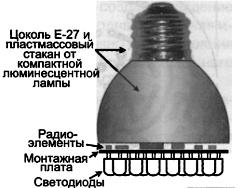
Figure 8
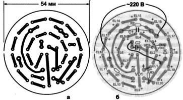
The printed circuit board on which all the parts are placed is made of foil fiberglass in any of the ways available at home. To install the LEDs, 0.8 mm diameter holes were drilled on the board, and 1.0 mm for the remaining parts. A circuit board drawing is shown in Figure 9.
Figure 9. The printed circuit board and the arrangement of parts on it.
The location of parts on the board is shown in Figure 9c. All parts except LEDs are installed on the side of the board, where there are no printed tracks. A jumper is also installed on the same side, also shown in the figure.
After installing all the parts on the side of the foil, LEDs are installed. Installation of LEDs should begin from the middle of the board, gradually moving to the periphery. The LEDs must be sealed in series, that is, the positive terminal of one LED is connected to the negative terminal of the other.
The diameter of the LED can be any within 3 ... 10 mm. In this case, the conclusions of the LEDs should be left at least 5 mm long from the board. Otherwise, the LEDs can simply be overheated when soldering. The duration of soldering, as recommended in all manuals, should not exceed 3 seconds.
After the board is assembled and adjusted, its conclusions must be soldered to the base, and the board itself is inserted into the case. In addition to the indicated case, it is possible to use a more miniature case, however, it will be necessary to reduce the size of the printed circuit board, not forgetting, however, the dimensions of the capacitors C1 and C2.
See also: LED lamp repair history
The simplest LED lamp design
Such a circuit is shown in Figure 10.
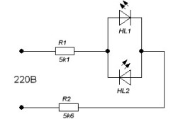
Figure 10. The simplest LED lamp design.
The circuit contains a minimum number of parts: only 2 LEDs and quenching resistor. The diagram shows that the LEDs are turned on in parallel - in parallel. With this inclusion, each of them protects the other from the reverse voltage, which is small for the LEDs, and the mains voltage clearly can not stand it. In addition, such a double inclusion will increase the flicker frequency of the LED lamp to 100 Hz, which will not be noticeable to the eye and will not bore the eyesight. It is enough to recall here how, in order to save money, ordinary incandescent lamps were connected through a diode, for example, in entrances. They acted very unpleasantly on vision.
If two LEDs are not available, then one of them can be replaced with a conventional rectifier diode, which will protect the emitting diode from the reverse voltage of the network. The direction of its inclusion should be the same as that of the missing LED. With this inclusion, the flicker frequency of the LED will be 25 Hz, which will be noticeable to the eye, as already described just above.
To limit the current through the LEDs at the level of 20 mA, the resistor R1 must have a resistance in the range of 10 ... 11 KOhm. At the same time, its power should be at least 5 watts. To reduce heating, it can be composed of several, best of all three, 2 W resistors.
LEDs can be used the same as those mentioned in previous schemes or which can be purchased. When buying, you should accurately know the brand of the LED in order to determine its rated direct current. Based on the magnitude of this current, the resistance of the resistor R1 is selected.
The design of the lamp assembled according to this scheme differs little from the two previous ones: it can also be made in the housing from an unusable energy-saving fluorescent lamp. The simplicity of the circuit does not even imply the presence of a printed circuit board: the parts can be connected by wall mounting, therefore, as they say in such cases, the design is arbitrary.
See also at e.imadeself.com
:


