Categories: Practical Electronics, Home automation
Number of views: 182917
Comments on the article: 10
The easiest twilight switch (photo relay)
 The modern elemental base of electronics greatly simplifies circuitry. Even a normal twilight switch can now be assembled from just three parts.
Quite often, situations arise when, after dark, the inclusion of lighting is required. This may be the entrance to the entrance of the apartment building, the porch and the courtyard of a private household, or simply lighting the house number. This inclusion is usually carried out using twilight switch (photo relay).
There are a lot of similar schemes developed, both in amateur and in industrial conditions. Like everything else, these designs have their positive and negative properties. Some of the negative properties are such as the need for an external constant voltage source (+12 V), or the complexity of the circuit.
The disadvantages of such devices should also include the use of a relay, whose contacts simply burn out over time. There are a lot of simple and cheap twilight switches on sale in electrical goods stores, but the quality of their work is often unsatisfactory. Such difficulties often push consumers away from using such switches.
Functional diagram of twilight switches simple enough. Conventionally, it can be divided into three components: photocell (photoresistor, phototransistor, photodiode), threshold device (comparator)output device (relay or triac) In daylight, the resistance of the photoresistor is small, so the voltage on it does not exceed the threshold of the comparator. And so the load (lighting) is off.
With a decrease in illumination, the resistance of the photoresistor increases and the voltage on it increases. At a certain point, the voltage level at the photoresistor reaches the threshold of the comparator, which with the help of the relay turns on the lighting.
It would seem that the operation algorithm is quite simple, and it is not difficult to implement it. But, nevertheless, some circuits are quite complex, and if performed on transistors without the use of microcircuits, they may contain a dozen or other parts.
At the same time, the modern elemental base of electronics allows you to create very simple and functional photo relay circuits. This is achieved by integration (integration) of some elements into others. An example of such integration is one of the developments of the company Teccor Electronics.
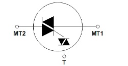
This is a triac or, in a foreign manner, a triac, with a built-in (integrated) symmetrical dinistor acting as a threshold device. Such a device is called Quadrac. Its internal circuit is shown in Figure 1.
It is easy to see that this is a common triac, only a symmetric dinistor is connected in series to the control electrode circuit. According to the reference data (DataSheet), the threshold voltage of the integrated dinistor is in the range 33 ... 43 V.
Figure 1. Quadrac triac. The scheme is basic.
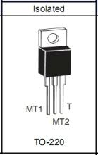
Quadrac triacs are available in a standard TO-220 enclosure with an insulated crystal, as shown in Figure 2. They do not differ in design or appearance from conventional triacs. Even the pin layout is the same.
Figure 2. Triac type Quadrac. Appearance and arrangement of conclusions.
Depending on the specific model, Quadrac differ in maximum currents and voltages: currents are in the range of 4 ... 15 A, and permissible voltages are 200 ... 600 V. Special Quadrac are intended for use in highly inductive circuits. These models have the letter H at the end of the designation, for example Q6006LTH.
In general, to understand the marking of these triacs is quite simple. We will deal with it on the example of the just mentioned Q6006LTH.
The first letter Q, as you might guess, is borrowed from Quadrac and means that it is nothing more than a triac with a built-in dinistor.
The two digits following the first letter, in this case 60, mean that the operating voltage of this device is 600 V.
The last two digits 06 indicate that the maximum working current is 6 A.
The letter H at the end of the designation is information that this type of device can be used to control an inductive load, such as a magnetic starter coil.
When using a conventional triac in this case (without the letter H at the end of the designation), terminals 1 and 2 of Q1 (see the diagram in Figure 3) must be shunted by an RC circuit consisting of a 100 Ohm resistor and a 0.1 MkF capacitor connected in series. Wherein power resistor must be at least two watts, and the operating voltage of the capacitor is not lower than 600 V. The capacitor, as always in such cases, is a film type K-73-17. If these measures are not taken, then the starter coil will not be held as it should: a loud battle bell will result.
Q4015LTH. Judging by the designation, such a Quadrac has an operating voltage of 400 V, a maximum current of 15 A, and is designed to work with a highly inductive load.
The purpose of a conventional triac is to switch the alternating current using voltage pulses on the control electrode. When used in a twilight switch, a threshold device is required, as described above.
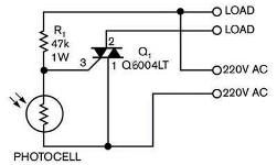
A quadrac triac contains a threshold device within itself. This is an integrated dinistor with a response threshold of about 40 V. In order to create a twilight switch on such a triac, just two parts are enough. In the diagram, this is the resistor R1 and the photocell (photoresistor) PHOTOCELL. Such a scheme is shown in Figure 3.
Figure 3. A simple twilight switch.
When the photocell is illuminated, its resistance is small (not more than a few kOhm), the voltage on the quadrock control electrode is insignificant, which is why it is in a closed state. In this case, the bulb, of course, does not light.
With a decrease in illumination, the resistance of the photoresistor increases, so voltage pulses appear on the control electrode, the amplitude of which increases with the onset of darkness. When the pulse amplitude reaches 40 V, the triac opens, the lamp lights up.
In the described device, a quadrack is used (such a name is quite applicable, even Yandex finds what it needs from it) with an operating voltage of 600 V and a current of 4 A. With these parameters, a load with a power of 400 ... 500 W can be turned on, and even not required installation of a triac on a radiator. If you install it on a radiator with an area of about 100 square centimeters, then the load power can be increased to 750 watts.
If you plan to connect a load with more power, then Quadrac should be used for operating currents of 6, 8, 10 or 15 A.
The setup of the device is reduced to the selection of the resistance of the resistor R1, it depends on this value at what illumination the device will operate. The resistance value of the resistor R1 also depends on the photocell of the twilight switch, therefore, the value indicated in the diagram should be taken as an approximate one. The type of photoresistor in the diagram is not indicated. You can use any, for example SF3-1, FSK-7 or FSK-G1.
Setting up a homemade photo relay can be performed by lighting a photocell with a conventional incandescent lamp connected through power regulator.
Boris Aladyshkin
See also at e.imadeself.com
:


