Categories: Practical Electronics, Novice electricians
Number of views: 331096
Comments on the article: 18
Triacs: From Simple to Complex
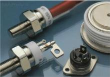 In 1963, a large family of Trinistors appeared another "relative" - triac. How does he differ from his "brothers" - trinistors (thyristors)? Remember the properties of these devices. Their work is often compared with the action of an ordinary door: the device is locked - there is no current in the circuit (the door is closed - there is no passage), the device is open - an electric current appears in the circuit (the door opened - enter). But they have a common flaw. Thyristors pass current only in the forward direction - this way an ordinary door easily opens "from itself", but no matter how much you pull it towards you - in the opposite direction, all efforts will be futile.
By increasing the number of semiconductor layers of the thyristor from four to five and equipping it with a control electrode, scientists found that a device with such a structure (later called a triac) is capable of passing electric current in both forward and reverse directions.
Look at figure 1, depicting the structure of the semiconductor layers of the triac. Outwardly, they resemble the transistor structure p-n-r type, but differ in that they have three additional areas with nconductivity. And here's what is interesting: it turns out that two of them, located at the cathode and anode, perform the functions of only one semiconductor layer - the fourth. Fifth forms an area with n-conductivity lying near the control electrode.
It is clear that the operation of such a device is based on more complex physical processes than other types of thyristors. To better understand the principle of the triac operation, we will use its thyristor analog. Why exactly thyristor? The fact is that the separation of the fourth semiconductor layer of the triac is not accidental. Due to this structure, in the forward direction of the current flowing through the device, the anode and cathode perform their main functions, and if they are reversed, they seem to swap places - the anode becomes a cathode, and the cathode, on the contrary, becomes an anode, that is, a triac can be considered as two counter-parallel thyristor switched on (Fig. 2).
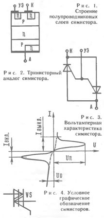
Trinistor analogue triac
Imagine that a trigger signal is applied to the control electrode. When the voltage at the anode of the device is positive polarity and negative at the cathode, an electric current will flow through the left trinistor. If the polarity of the voltage across the power electrodes is reversed, the right trinistor will turn on. The fifth semiconductor layer, like a traffic controller controlling the movement of cars at an intersection, sends a trigger signal, depending on the phase of the current, to one of the trinistors. In the absence of a trigger signal, the triac is closed.
On the whole, its action can be compared, for example, with a revolving door at a metro station - in which direction you push it, it will certainly open. Indeed, we apply the unlocking voltage to the control electrode of the triac - “push” it, and the electrons, like passengers hurrying to board or exit, will flow through the device in the direction dictated by the polarity of the anode and cathode.
This conclusion is confirmed by the current-voltage characteristic of the device (Fig. 3). It consists of two identical curves rotated 180 ° relative to each other. Their shape corresponds to the current-voltage characteristic of the dynistor, and the regions of the nonconducting state, like that of the trinistor, can be easily overcome if a trigger voltage is applied to the control electrode (changing sections of the curves are shown by dashed lines).
Due to the symmetry of the current-voltage characteristic, the new semiconductor device was called a symmetric thyristor (in short - a triac). It is sometimes called a triac (a term that comes from English).
The triac has inherited from its predecessor, the thyristor, all its best properties. But the most important advantage of the novelty is that two semiconductor devices are immediately located in its case. Judge for yourself. To control the DC circuit, one thyristor is required, for the alternating current circuit of the devices there must be two (turned on in parallel). And if we take into account that each of them needs a separate source of unlocking voltage, which, moreover, must turn on the device exactly at the moment of changing the phase of the current, it becomes clear how difficult such a control unit will be. For the triac, the kind of current does not matter. Only one such device with a source of unlocking voltage is enough, and a universal control device is ready. It can be used in a DC or AC power circuit.
The close relationship between the thyristor and the triac led to the fact that these devices had a lot in common. So the electrical properties of the triac are characterized by the same parameters as the thyristor. They are also marked in the same way - by the letters KU, a three-digit number and the letter index at the end of the designation. Sometimes triacs are designated somewhat differently - by the letters TC, which means "thyristor is symmetrical."
The conventional graphic designation of triacs on circuit diagrams is shown in Figure 4.
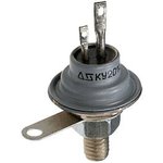 For a practical acquaintance with triacs, we will choose devices of the KU208 series - triode symmetric thyristors of the p-p-p-p type. The types of devices are indicated by the letter indices in their designation - A, B, C or G. The constant voltage that the triac with the index A can withstand when closed is 100 V, B - 200 V, V - 300 V and G - 400 V. The remaining parameters of these devices are identical: the maximum direct current in the open state is 5 A, the pulse current is 10 A, the leakage current in the closed state is 5 mA, the voltage between the cathode and the anode in the conducting state is -2 V, the value of the unlocking voltage at the control electrode 5 V at 160 mA, dissipated by the housing The instrument power- 10 W, the maximum operating frequency - 400 Hz.
And now let's turn to electric lighting devices. There is nothing easier to manage the work of any of them. I pressed, for example, the switch key - and in the room a chandelier lit up, pressed again - went out. Sometimes, however, this advantage unexpectedly turns into a disadvantage, especially if you want to make your room cozy, create a feeling of comfort, and for this it is so important to choose the right lighting. Now, if the glow of the lamps changed smoothly ...
It turns out that there is nothing impossible. It is only necessary instead of a conventional switch to connect an electronic device that controls the brightness of the lamp. The functions of the controller, "commander" of the lamps, in such a device performs a semiconductor triac.
You can build a simple control device that will help you control the brightness of the glow of a table lamp or a chandelier, change the temperature of a hot plate or a tip of a soldering iron using the circuit shown in Figure 5.
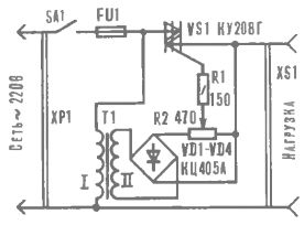
Fig. 5. Schematic diagram of the regulator
The transformer T1 converts the mains voltage of 220 V into 12 - 25 V. It is rectified by the diode block VD1-VD4 and fed to the control electrode of the triac VS1. The resistor R1 limits the current of the control electrode, and the magnitude of the control voltage is controlled by a variable resistor R2.
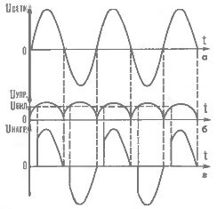
Fig. 6. Timing diagrams of voltage: a - in the network; b - on the control electrode of the triac, c - on the load.
To make it easier to understand the operation of the device, we construct three time diagrams of voltages: mains, at the control electrode of the triac and at the load (Fig. 6). After the device is connected to the network, an alternating voltage of 220 V is supplied to its input (Fig. 6a). At the same time, a negative sinusoidal voltage is applied to the control electrode of the triac VS1 (Fig. 66). At the moment when its value exceeds the switching voltage, the device will open and the mains current will flow through the load.After the value of the control voltage becomes lower than the threshold, the triac remains open due to the fact that the load current exceeds the holding current of the device. At the moment when the voltage at the input of the regulator changes its polarity, the triac closes. The process is then repeated. Thus, the voltage at the load will have a sawtooth shape (Fig. 6c)
The larger the amplitude of the control voltage, the earlier the triac will turn on, and therefore, the longer the current pulse will be in the load. Conversely, the smaller the amplitude of the control signal, the shorter the duration of this pulse. At the extreme left position of the engine variable resistor R2 according to the diagram, the load will absorb the full "portions" of power. If the R2 regulator is turned in the opposite direction, the amplitude of the control signal is below the threshold value, the triac will remain in the closed state and the current will not flow through the load.
It is easy to guess that our device regulates the power consumed by the load, thereby changing lamp brightness or temperature of the heating element.
You can apply the following elements to your device. Triac KU208 with the letter B or G. Diode block KTs405 or KTs407 with any letter index, four are also suitable semiconductor diode series D226, D237. Permanent resistor - MLT-0.25, variable - SPO-2 or any other power not less than 1 W. ХР1 - standard network plug, XS1 - socket. The T1 transformer is designed for a secondary winding voltage of 12-25 V.
If there is no suitable transformer, make it yourself. The core is made of Ш16 plates, the set thickness is 20 mm, winding I contains 3300 turns of PEL-1 0.1 wire, and winding II contains 300 turns of PEL-1 0.3.
Toggle switch - any network fuse, must be designed for the maximum load current.
The regulator is assembled in a plastic case. A toggle switch, a variable resistor, a fuse holder and a socket are mounted on the top panel. A transformer, a diode block and a triac are installed at the bottom of the case. The triac must be equipped with a heat dissipating radiator with a thickness of 1 - 2 mm and an area of at least 14 cm2. Drill a hole for the power cord in one of the side walls of the chassis.
The device does not need to be adjusted, and with proper installation and serviceable parts, it starts working immediately after it is connected to the network.
USING THE REGULATOR, DO NOT FORGET ABOUT SAFETY PRECAUTIONS. YOU CAN OPEN THE HOUSING ONLY BY DISCONNECTING THE APPLIANCE FROM THE NETWORK!
V. Yantsev.
See also at e.imadeself.com
:
