Categories: Featured Articles » Sharing experience
Number of views: 119762
Comments on the article: 6
How to check the diode and thyristor. 3 easy ways
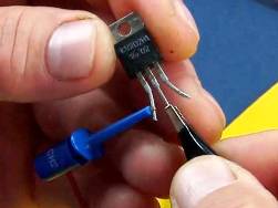 Among home masters and craftsmen, the need periodically arises to determine the operability of a thyristor or triac, which are widely used in household appliances to change the speed of electric motor rotors, in power regulators of lighting devices, and in other devices.
How the diode and thyristor work
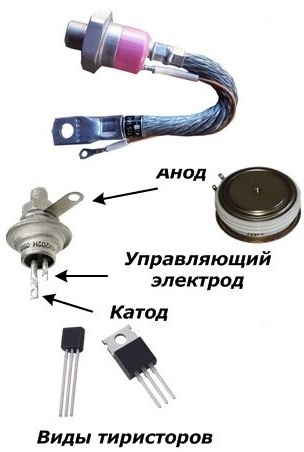
Before describing the verification methods, we recall the thyristor device, which is not for nothing called a controlled diode. This means that both semiconductor elements have almost the same device and work in exactly the same way, except that the thyristor has a limitation - control through an additional electrode by passing an electric current through it.
The thyristor and the diode pass the current in one direction, which in many designs of Soviet diodes is indicated by the direction of the angle of the triangle on the mnemonic symbol located directly on the case. In modern diodes in a ceramic case, the cathode is usually marked by applying an annular strip near the cathode.
Check performance diode and thyristor can pass current load through them. For this, it is allowed to use an incandescent bulb from old flashlights, the thread of which glows from a current of the order of 100 mA or less. When current flows through the semiconductor, the light will be on, but if not, it will not.
Read more on how diodes and thyristors work here:How semiconductor diodes are arranged and work, Thyristor Power Regulators
How to check the health of the diode
Usually, an ohmmeter or other devices having the function of measuring active resistances are used to assess the health of the diode. Applying voltage to the electrodes of the diode in the forward and reverse direction, judge the magnitude of the resistance. With the p-n junction open, the ohmmeter will show a value of zero, while with the junction closed, it will show infinity.
If an ohmmeter is not available, then the diode can be checked for health using a battery and a light bulb.
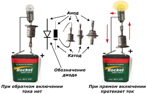
Diode Health Check Circuit
Before checking the diode in this way, it is necessary to take into account its power. Otherwise, the load current can destroy the internal structure of the crystal. To evaluate low-power semiconductors, it is recommended to use an LED instead of a light bulb and reduce the load current to 10-15 mA.
How to check the thyristor
There are several methods to evaluate the performance of a thyristor. Consider the three most common and affordable at home.
Battery and Light Method
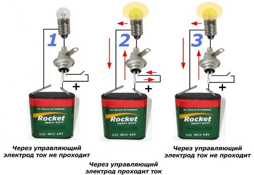
Thyristor Health Check Circuit
When using this method, the current load of 100 mA created by the light bulb on the internal circuits of the semiconductor should also be estimated and applied for a short time, especially for control electrode circuits.
The figure does not show a check for a short circuit between the electrodes. This malfunction is almost never encountered, but to be completely sure of its absence, you should try to pass a current through each pair of all three thyristor electrodes in the forward and reverse directions. This will take only a few seconds of time.
When assembling the circuit according to the first embodiment, the semiconductor junction of the device does not pass current, and the light does not light. This is its main difference in operation from a conventional diode.
To open the thyristor, it is enough to apply a positive source potential to the control electrode. This option is shown in the second diagram. A healthy appliance will open an internal circuit and current will flow through it. This will be indicated by the glow of the filament of the bulb.
The third diagram shows the power failure from the control electrode and the passage of current through the anode and cathode.This is due to the excess current holding the internal junction.
The holding effect is used in power control circuits when a short-term current pulse from a phase-shifting device is applied to the control electrode to open the thyristor controlling the magnitude of the alternating current.
A light bulb in the first case or the absence of its glow in the second indicates a thyristor malfunction. But the loss of luminescence when the voltage is removed from the contact of the control electrode can be caused by the magnitude of the current flowing through the anode-cathode circuit less than the limit value of retention.
An open circuit through the anode or cathode brings the thyristor to a closed state.
Test method with a homemade appliance
It is possible to reduce the risks of damage to internal circuits of semiconductor junctions when checking low-power thyristors by selecting the values of currents through each circuit. To do this, it is enough to assemble a simple electrical circuit.
The figure shows a device designed to operate from 9-12 volts. When using other supply voltages, a calculation of the resistance values R1-R3 should be done.
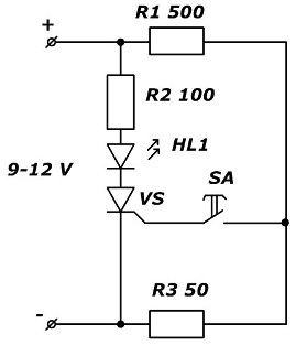
Fig. 3. Scheme of the device for checking thyristors
A current of about 10 mA is sufficient through the HL1 LED. With frequent use of the device for connecting the thyristor VS electrodes, it is desirable to make contact sockets. The SA button allows quick switching of the control electrode circuit.
If the LED lights up until the SA button is pressed or if it is not lit, this is a clear sign of thyristor damage.
Method using a tester, multimeter or ohmmeter
The presence of an ohmmeter simplifies the process of checking the thyristor and resembles the previous circuit. In it, the device’s batteries serve as a current source, and instead of the LED glow, the arrow deviation is used for analog models or digital readings on the scoreboard for digital devices. With indications of high resistance, the thyristor is closed, and at low values it is open.
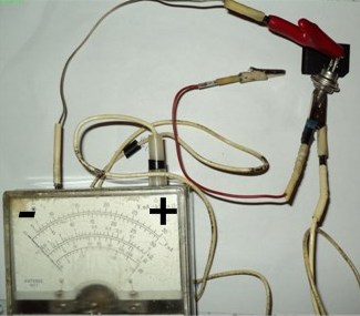
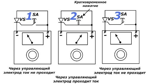
Thyristor test circuit with an ohmmeter
Here, all the same three stages of the test are evaluated with the SA button depressed for a short time and again disabled. In the third case, the thyristor is likely to change its behavior due to the small value of the tested current: it is not enough to hold it.
Low resistance in the first case and high in the second indicate violations of the semiconductor transition.
The ohmmeter method allows you to check the health of semiconductor junctions without evaporating the thyristor from most circuit boards.
The design of the triac can be conventionally represented as consisting of two thyristors, connected counterclockwise to each other. His anode and cathode do not have strict polarity like a thyristor. They work with alternating electric current.
The quality of the triac status can be evaluated by the verification methods described above.
Read also on this topic: How to measure voltage, current, resistance with a multimeter, check diodes and transistors
See also at e.imadeself.com
:
