Categories: Practical Electronics, Electrician Secrets
Number of views: 338,506
Comments on the article: 24
DIY do-it-yourself thermostat
 Unusual use of the adjustable zener diode TL431. Simple temperature controller. Description and scheme
Anyone who has ever been involved in repairs of modern computer power supplies or various chargers - for cell phones, for charging “finger” AAA and AA batteries, a small detail is well known TL431. This is the so-called adjustable zener diode (domestic analogue of KR142EN19A). Here it truly can be said: "Small spool, yes dear."
The logic of the Zener diode is as follows: when the voltage on the control electrode exceeds 2.5 V (set by the internal reference voltage), the Zener diode, which is essentially a microcircuit, is open.
In this state, current flows through it and the load. If this voltage becomes slightly less than the specified threshold, the zener diode closes and disconnects the load.
When such a zener diode is used in power sources, the emitting LED of the optocoupler controlling the power transistor is most often used as a load.
This is in cases where galvanic isolation of the primary and secondary circuits is necessary. If such isolation is not required, then the zener diode can directly control the power transistor.
The output power of the zener diode microcircuit is such that, with its help, it is possible to control a low-power relay. This is what allowed it to be used in the construction of a temperature regulator.
In the proposed design, the zener diode is used as a comparator. At the same time, it has only one input: a second input is not required for supplying the reference voltage, since it is generated inside this microcircuit.
This solution allows you to simplify the design and reduce the number of parts. Now, as in the description of any design, a few words should be said about the details and actually about the principle of operation of this thermostat.
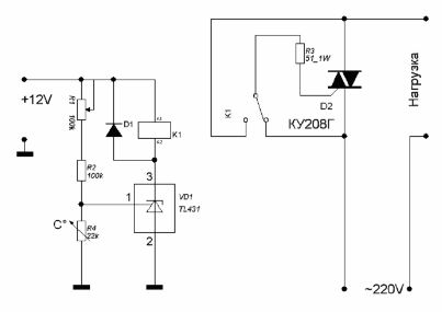
Simple tremoregulator circuit
The voltage at the control electrode 1 is set using the divider R1, R2 and R4. As R4 is used thermistor with negative TCR, therefore, when heated, its resistance decreases. When pin 1 voltage above 2.5V chip is open, the relay is on.
Relay contacts include triac D2, which includes the load. With increasing temperature, the resistance of the thermistor drops, due to which the voltage at terminal 1 becomes lower than 2.5V - the relay is turned off, the load is turned off.
Using a variable resistor R1, the temperature of the thermostat is set.
The temperature sensor should be located in the temperature measuring area: if it is, for example, electric boiler, then the sensor must be fixed to the pipe leaving the boiler.
The inclusion of a triac using a relay provides galvanic isolation of the thermistor from the network.
Thermistor type KMT, MMT, CT1. As a relay, it is possible to use RES-55A with a winding of 10 ... 12V. The KU208G triac allows you to turn on the load up to 1.5 kW. If the load is not more than 200W, the triac can operate without the use of a radiator.
Boris Aladyshkin
See also at e.imadeself.com
:

