Categories: Featured Articles » Practical Electronics
Number of views: 214,227
Comments on the article: 7
Indicators and signaling devices on an adjustable zener diode TL431
 The TL431 integrated stabilizer is mainly used in power supplies. However, for it you can find many more applications. Some of these schemes are provided in this article.
This article will talk about simple and useful devices made using Chips TL431. But in this case, you should not be afraid of the word “microcircuit”, it has only three conclusions, and outwardly it looks like a simple low-power transistor in the TO90 package.
First a bit of history
It so happened that all electronic engineers know the magic numbers 431, 494. What is this?
TEXAS INSTRUMENTS was at the forefront of the semiconductor era. All this time, she has been in the first place in the list of world leaders in the production of electronic components, firmly holding herself in the top ten or, as they say more often, in the world ranking TOP-10. The first integrated circuit was created back in 1958 by Jack Kilby, an employee of this company.
Now TI produces a wide range of microcircuits, the name of which begins with the TL and SN prefixes. These are respectively analog and logical (digital) microcircuits, which have forever entered the history of TI and still find wide application.
 Among the very first in the list of "magic" chips should probably be considered adjustable voltage regulator TL431. In the three-pin case of this microcircuit, 10 transistors are hidden, and the function performed by it is the same as a conventional zener diode (Zener diode).
But due to this complication, the microcircuit has higher thermal stability and increased slope characteristics. Its main feature is that with external divider stabilization voltage can be changed within 2.5 ... 30 V. For the latest models, the lower threshold is 1.25 V.
TL431 was created by TI employee Barney Holland in the early seventies. Then he was engaged in copying the stabilizer chip of another company. We would say ripping, not copying. So Barney Holland borrowed a reference voltage source from the original microcircuit, and on its basis created a separate stabilizer microcircuit. At first it was called TL430, and after some improvements it was called TL431.
Since then, a lot of time has passed, and now there is not a single computer power supply, wherever it finds application. It also finds application in almost all low-power switching power supplies. One of these sources is now in every home, is Charger for cell phones. Such longevity can only be envied. Figure 1 shows the functional diagram of the TL431.

Figure 1. Functional diagram of TL431.
Barney Holland also created the no less famous and still in demand TL494 chip. This is a push-pull PWM controller, on the basis of which many models of switching power supplies were created. Therefore, the number 494 also rightly refers to the "magic."
Now let's move on to the consideration of various designs based on the TL431 chip.
Indicators and Signalers
The TL431 chip can be used not only for its intended purpose as a zener diode in power supplies. On its basis, it is possible to create various light indicators and even sound signaling devices. Using such devices, you can track many different parameters.
First of all, it’s just electric voltage. If any physical quantity with the help of sensors is presented in the form of voltage, then it is possible to make a device that monitors, for example, the water level in the tank, temperature and humidity, illumination or pressure of a liquid or gas.
Over Voltage Alarm
The operation of such a signaling device is based on the fact that when the voltage at the control electrode of the zener diode DA1 (pin 1) is less than 2.5 V, the zener diode is closed, only a small current flows through it, usually no more than 0.3 ... 0.4 mA. But this current is enough for a very weak glow of the HL1 LED. To prevent this phenomenon, it is enough to connect a resistor with a resistance of about 2 ... 3 KOhm parallel to the LED. The overvoltage detector circuit is shown in Figure 2.

Figure 2. Overvoltage detector.
If the voltage at the control electrode exceeds 2.5 V, the zener diode will open and the HL1 LED will light up. the necessary current limitation through the zener diode DA1 and the LED HL1 provides the resistor R3. The maximum current of the zener diode is 100 mA, while the same parameter for the HL1 LED is only 20 mA. It is from this condition that the resistance of the resistor R3 is calculated. more precisely, this resistance can be calculated using the formula below.
R3 = (Upit - Uhl - Uda) / Ihl. The following notation is used here: Upit - supply voltage, Uhl - direct voltage drop on the LED, Uda voltage on an open circuit (usually 2V), Ihl LED current (set within 5 ... 15 mA). Also, do not forget that the maximum voltage for the zener diode TL431 is only 36 V. This parameter also cannot be exceeded.
Alarm Level
The voltage at the control electrode at which the LED HL1 (Uз) lights up is set by the divider R1, R2. divider parameters are calculated by the formula:
R2 = 2.5 * R1 / (Uz - 2.5). For a more precise adjustment of the response threshold, you can install a tuning trim instead of the resistor R2, with a nominal value of one and a half times more than what was calculated. After the tincture is made, it can be replaced by a constant resistor, the resistance of which is equal to the resistance of the introduced part of the tuning.
Sometimes it is required to control several voltage levels. In this case, three such signaling devices will be required, each of which is configured for its own voltage. Thus, it is possible to create a whole line of indicators, a linear scale.
To power the display circuit, consisting of LED HL1 and resistor R3, you can use a separate power source, even unstabilized. In this case, the controlled voltage is applied to the terminal of the resistor R1, which should be disconnected from the resistor R3. With this inclusion, the controlled voltage can range from three to several tens of volts.
Undervoltage indicator

Figure 3. Undervoltage indicator.
The difference between this circuit and the previous one is that the LED is turned on differently. This inclusion is called inverse, since the LED lights up when the chip is closed. If the controlled voltage exceeds the threshold set by the divider R1, R2, the microcircuit is open, and the current flows through the resistor R3 and pins 3 - 2 (cathode – anode) of the microcircuit.
On the chip in this case there is a voltage drop of 2 V, which is not enough to ignite the LED. To ensure that the LED is not guaranteed to light, two diodes are installed in series with it. Some types of LEDs, for example blue, white and some types of green, light up when the voltage exceeds 2.2 V. In this case, jumpers made of wire are installed instead of diodes VD1, VD2.
When the monitored voltage becomes less than that set by the divider R1, R2 the microcircuit closes, the voltage at its output will be much more than 2 V, so the HL1 LED will light up.
If you want to control only the voltage change, the indicator can be assembled according to the scheme shown in Figure 4.
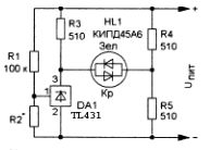
Figure 4. Voltage change indicator.
This indicator uses a two-color LED HL1. If the monitored voltage exceeds the threshold value, the red LED lights up, and if the voltage is low, the green one lights up.
In the case when the voltage is near a predetermined threshold (approximately 0.05 ... 0.1 V), both indicators are extinguished, since the transfer characteristic of the zener diode has a well-defined slope.
If you want to monitor the change in any physical quantity, then the resistor R2 can be replaced by a sensor that changes the resistance under the influence of the environment. A similar device is shown in Figure 5.

Figure 5. Scheme of monitoring environmental parameters.
Conventionally, on one diagram several sensors are shown at once. If it will be phototransistorit will turn out photo relay. While the illumination is large, the phototransistor is open, and its resistance is small. Therefore, the voltage at the control terminal DA1 is less than the threshold; as a result, the LED does not light.
As the illumination decreases, the resistance of the phototransistor increases, which leads to an increase in the voltage at the control terminal DA1. When this voltage exceeds the threshold (2.5 V), the zener diode opens and the LED lights up.
If, instead of a phototransistor, a thermistor, for example, an MMT series, is connected to the input of the device, a temperature indicator is obtained: when the temperature drops, the LED will light up.
The same scheme can be used as humidity sensor, for example, land. To do this, instead of a thermistor or a phototransistor, stainless steel electrodes should be connected, which at some distance from each other should be thrust into the ground. When the earth dries to the level determined during setup, the LED will light up.
The threshold of the device in all cases is set using a variable resistor R1.
In addition to the listed light indicators on the TL431 chip, it is also possible to assemble an audio indicator. A diagram of such an indicator is shown in Figure 6.

Figure 6. Sound liquid level indicator.
To control the level of a liquid, such as water in a bath, a sensor made of two stainless plates, which are located at a distance of several millimeters from each other, is connected to the circuit.
When water reaches the sensor, its resistance decreases, and the chip enters the linear mode through the resistors R1 R2. Therefore, self-generation occurs at the resonant frequency of the piezoceramic emitter HA1, at which the sound signal will sound.
As the emitter, you can use the radiator ZP-3. the device is powered from a voltage of 5 ... 12 V. This allows you to power it even from galvanic batteries, which makes it possible to use it in different places, including in the bathroom.
The main scope of the TL434 chip, of course, power supplies. But, as we see, the capabilities of the microcircuit are not limited to this alone.
Boris Aladyshkin
See also at e.imadeself.com
: