Categories: Featured Articles » Practical Electronics
Number of views: 140904
Comments on the article: 10
Simple power control for smooth lamp on
 An article on how to make a device for smooth turning on lamps using the KR1182PM1 chip.
Power controllers are widely used. The simplest of them can be considered a conventional diode, connected in series with the load. This "regulation" is most often used in two cases: as a means of extending the life of an incandescent lamp (usually on staircases in staircases) and to prevent overheating soldering iron. In other cases, the regulators serve to change the power in the load over a wide range.
Specialized chip KR1182PM1
There are a lot of designs of regulators, from the simplest to the most complex. One of the ways to create simple, reliable and multi-functional controllers was the creation of a specialized chip KR1182PM1.
The microcircuit is a phase regulator, structurally made in the housing design POWEP-DIP. The case is sixteen-pin, the pin pitch is metric, and pins 4, 5 and 12, 13 are not used, although inside the microcircuit they are connected to the crystal mechanically. Their purpose is to remove heat from the crystal. Also, pins 1, 2, and 7, 8 are not used for connection. The microcircuit housing drawing is shown in Figure 1.

Figure 1. POWEP-DIP Chip Case
The scope of the KR1182PM1 chip is very wide. Firstly, it is the control of the operation of incandescent lamps, which provides for both the actual regulation of power and the provision of smooth on and off.
Secondly, KR1182PM1 is successfully used to control the frequency of rotation of electric motors.
And thirdly, to control powerful thyristors and triacs, which makes it possible to increase the load power. Without connecting external thyristors, the microcircuit can switch power no more than 150 W, which, you see, is not so small at such sizes.
The device microcircuit KR1182PM1
The internal structure of the chip is quite complicated. It contains seventeen transistors, six diodes and a dozen resistors. Therefore, in this article we will not look at the microcircuit in great detail, but only consider its individual nodes. The internal structure of the chip is shown in Figure 2.

Figure 2. The internal structure of the KR1182PM1 chip.
To control the load inside the microcircuit, there are two trinistors (thyristors), each of which is assembled in the form of a transistor analog. In the diagram, these are transistors VT1, VT2, and VT3, VT4. To ensure operation on alternating voltage, the trinistors are switched in counter-parallel, as well as ordinary thyristors.
On transistors VT15 ... VT17, a control unit is assembled, which is connected through dividing diodes VD6 and VD7 to the control electrodes of the trinistors.
In addition to these elements, the controller has a built-in thermal protection unit, which limits the output current, thereby protecting the microcircuit from overloads and failure.
There are very few external parts connected to the chip. Firstly, these are capacitors C1 and C2. Their purpose is to provide a certain delay in turning on the thyristors relative to the moment when the mains voltage passes through zero. In addition, they do not allow thyristors to open when the entire device is connected to the network.
Secondly, it is a control circuit connected to pins 3 and 6. The meaning of its work is as follows. When the mains voltage is turned on, capacitor C3 is not charged, so it closes terminals 3 and 6 almost short, so the load is disconnected. The capacitor begins to charge smoothly from a current generator made on transistors VT11 and VT12. as it is charged, the brightness of the EL1 lamp also increases smoothly from zero to maximum.
If you close the switch SB1, the capacitor C3 will gradually discharge, and the brightness of the lamp, accordingly, decrease until it goes out. Capacitor C3 can be in the range of 200 ... 500 uF. In the first case, the turn-on delay will visually be imperceptible, in the second it reaches several seconds. Resistor R1 can also have a value ranging from 100 ohms to tens of KOhm, which affects the time of smooth shutdown.
It is known that an incandescent lamp with a power of 150 W at the time of switching on consumes a current of up to 10 A, but if the turn-on delay is minimal and is not even visually noticeable, the inrush current when turned on does not exceed 2 A.
Figure 3 shows a simple hand-operated power regulator. In this case, it is best to use a variable resistor with a switch as a control resistor. The resistor should be turned on so that when SA1 is off, its resistance is minimal. Thus, when turning on and rotating the resistor R1, the power will change from zero to maximum. Such a regulator is suitable for controlling the brightness of the lamp, heating the soldering iron, and the speed of the domestic fan.
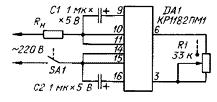
Figure 3. Power regulator on the KR1182PM1 chip.
As mentioned above, the power switched by a single chip is not more than 150 watts. If there is a need to increase the power of the device, you can use the parallel connection of two chips, as shown in Figure 4. Such a connection makes it possible to control a load of at least 300 watts.

Figure 4. Parallel connection of KR1182PM1 microcircuits.
The easiest way to make such a connection is by soldering the microcircuit into "two floors" - the additional microcircuit is simply soldered to the one that is already installed on the printed circuit board. In this case, no alteration of the board itself is required.
If the load power is such that even parallel connection of microcircuits cannot cope with it, then the power of the regulator can be significantly increased by connecting the load through triac. In this case, the microcircuit only controls the triac, and the latter controls the actual load. A diagram of such a connection is shown in Figure 5.

Figure 5. Connecting a powerful load through a triac.
As in the previous case, a variable resistor R1, combined with a switch SA1, is used as a regulating element. Only its connection is somewhat different. Load shedding occurs when contact group SA1 closes contacts 3 and 6 of the microcircuit. Accordingly, in this position, the resistor R1 must have a minimum resistance. It is appropriate to make such a reminder here - remember that if the contacts of microcircuit 3 and 6 are closed, then the load will be disconnected!
On this, the scope of the KR1182PM1 chip does not end far! Instead of a simple contact closing 3 and 6 conclusions can be connected phototransistor, - it turns out twilight switch with smooth inclusion. If a transistor optocoupler is connected to these conclusions, it becomes possible to stabilize the alternating voltage or control from the device on the microcontroller. All the possibilities simply can not be counted.
In the next part of the article, a three-phase motor soft start circuit based on KR1182PM1 microcircuits will be considered.
Boris Aladyshkin
See also at e.imadeself.com
: