Categories: Practical Electronics, Home automation
Number of views: 220157
Comments on the article: 16
Photo relay schemes for lighting control
 One of the tasks performed by photosensors, is an lighting control. Such schemes are called photo relay, most often this is a simple inclusion of lighting in the dark. For this purpose, a lot of circuits were developed by ham radio operators, here are some of them.
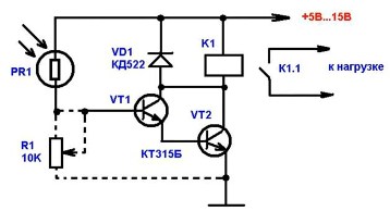
Probably the simplest scheme is shown in Figure 1. The number of parts in it is small, it will not work less, and the efficiency, read the sensitivity, is quite high.
This is achieved by the fact that transistors VT1 and VT2 are connected by a composite transistor circuit, also called a Darlington circuit. With this inclusion, the gain is equal to the product of the gain of the components of the transistors. In addition, such a circuit provides a high input impedance, which allows the connection of high-impedance signal sources, such as the PR1 resistor shown in the circuit.
Figure 1. Scheme of a simple photo relay
The operation of the circuit is quite simple. The resistance of the photoresistor PR1 with an increase in illumination decreases to several KOhms (the dark resistance is several MOhms), which will lead to the opening of the transistor VT1. Its collector current will open the transistor VT2, which will turn on the relay K1, which with its contact will turn on the load.
The diode VD1 protects the circuit from the self-induction EMF that occurs when the relay K1 is turned off. Thus, a very low-power signal of the photoresistor is converted to a signal sufficient to turn on the relay coil.
The sensitivity of this simple circuit is quite high, sometimes simply excessive. To reduce it, and adjust it to the necessary limits, you can add a variable resistor R1 to the circuit, shown in dotted form on the circuit.
The supply voltage is indicated within 5 ... 15V, - depends on the operating voltage of the relay. For a voltage of 6V, relays RES9, RES47 are suitable, and for voltage 12V, RES49, RES15. With the transistors indicated in the diagram, the current of the relay winding should not exceed 50 mA.
If instead of transistor VT2 we put, for example, KT815, then the output current may be larger, which will allow the use of more powerful relays. In general, the higher the supply voltage, the higher the sensitivity of the photo relay.
Photo relay circuit with photodiode
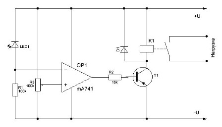
The scheme of this photo relay is shown in Figure 2.

Figure 2. Diagram of a photorelay with a photodiode
Like the previous one, it also contains a minimum number of parts, thanks to the application operational amplifier (OU). In this scheme, the opamp is turned on according to the scheme comparator (comparator). It is easy to see that the photodiode LED1 is turned on in the photodiode mode - the power is supplied so that the photodiode is biased in the opposite direction.
Therefore, with a decrease in the level of illumination, the resistance of the LED Led1 increases, which leads to a decrease in the voltage drop across the resistor R1, and therefore at the inverting input of the comparator OP1.
The voltage at the non-inverting input of the op-amp is set using a variable resistor R2, and is a threshold - sets the response threshold. As soon as the voltage at the inverting input becomes less than the threshold, a high voltage level will appear at the output of the comparator, which will open the transistor T1, which will turn on the relay K1.
The relay and transistor in this circuit can be selected, guided by the recommendations for the circuit shown in Figure 6. As a comparator, you can use the op amp type K140UD6, K140UD7 or the like. Any power source for the circuit is suitable, even a transformerless one, without galvanic isolation from the network. In this case, when setting up, you should be careful to comply with safety regulations. The ideal option is to use an isolation transformer to configure the circuit, or, as it is sometimes called safety transformer.
Setting up the device comes down to setting the threshold voltage in such a way that switching on occurs even at dusk. In order not to wait for this natural moment, it is possible in the darkened room to illuminate the photodiode with an incandescent lamp switched on through a thyristor power regulator. The same technique is suitable for tuning other photo relay circuits.
It is possible that when the photo relay is triggered, the relay will rattle. You can get rid of this phenomenon by connecting parallel to the coil electrolytic capacitor several hundred microfarads.
Photo relay on the chip
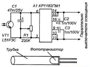
Specialized microchip KR1182PM1 represents a phase power regulator, the same as a conventional thyristor. A very important and valuable property of such a power regulator is that it is included in the circuit as a two-terminal device, without requiring an additional power cable: it simply turned on in parallel with the switch and everything already works! On the image 4 It is shown how a simple photo relay can be built on this microcircuit.

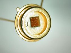
Fig. 3. The chip KR1182PM1
Picture 4. Photo relay circuit on the KR1182PM1 chip
The control pins of microcircuit 3 and 6. If you just connect a simple single-pole switch between them, then when it is closed, the load will turn off! If you open it, the load will connect. By the way, without additional external thyristors or triacs, and even without a radiator, the microcircuit can withstand loads of up to 150W. This is the case if there is no inrush current when the load is switched on, like incandescent lamps. An incandescent lamp in this embodiment can be turned on with a power of not more than 75W.
Just connect the switch to these pins no matter how, if only in combination with other parts. If you do not pay attention to the phototransistor and electrolytic capacitor, mentally leave only the variable resistor R1, then you just get a phase power regulator: when moving its motor up in the circuit, terminals 3 and 6 are short-circuited, thereby disconnecting the load, as mentioned above. When moving the engine down according to the scheme, the power in the load changes from 0 ... 100%. Everything is clear and simple here.
If we connect an electrolytic capacitor to these conclusions (we believe that there is no phototransistor in the circuit yet), then we get just a smooth switching on of the load. How?
The resistance of the discharged capacitor is small, so at first the control terminals of the microcircuit 3 and 6 are practically short-circuited and the load is disconnected. As the charge increases, the capacitor resistance increases (just recall the check of the capacitors with an ohmmeter), the voltage on it also grows, and the power in the load gradually increases. It turns out a device for smooth switching on the load. Moreover, the load will be supplied with power as much as the engine of the variable resistor R1 is introduced. When the device is disconnected from the network, the capacitor is discharged through the resistor R1, preparing the device for the next turn on. If the capacitor does not have time to discharge, then it will not turn on smoothly.
Now we got to the most important thing, to the photo relay. If you now connect a phototransistor to control pins 3 and 6, you get a photo relay. It works as follows. During high daylight, the phototransistor is open, so the resistance of its collector-emitter section is small, pins 3 and 6 are closed to each other, and the load is off.
With a smooth decrease in illumination in the evening hours, the phototransistor will gradually open, gradually increasing the power in the load, that is, in the lamp. There are no threshold elements in this circuit, so the lamp will light up and go out gradually.
So that the photo relay does not work at the moment when its own lamp turns on, it is desirable to protect the phototransistor from such a backlight. The easiest way to do this is with a plastic tube.
Read also on this topic: The easiest twilight do-it-yourself switch
Boris Aladyshkin
See also at e.imadeself.com
:


