Categories: Practical Electronics, Home automation
Number of views: 104853
Comments on the article: 13
Do-it-yourself thermostat for a cellar
Sensor selection for thermostat
 The temperature regulator in everyday life is used in a wide variety of devices, from the refrigerator to the irons and soldering irons. Probably, there is no radio amateur who would bypass such a scheme. Most often used as a temperature sensor or sensor in various amateur designs thermistors, transistors or diodes. The operation of such temperature controllers is quite simple, the operation algorithm is primitive, and as a result a simple electrical circuit.
Maintaining the set temperature is carried out by switching on / off heating element (TEN): as soon as the temperature reaches the set value, it works comparing device (comparator) and the heater is turned off. This principle of regulation is implemented in all simple regulators. It would seem that everything is simple and clear, but this is only until it comes to practical experiments.
The most difficult and time-consuming process in the manufacture of "simple" thermostats is to adjust to the desired temperature. To determine the characteristic points of the temperature scale, it is proposed to first immerse the sensor in a vessel with melting ice (this is zero degrees Celsius), and then in boiling water (100 degrees).
After this "calibration" by trial and error using a thermometer and a voltmeter, the necessary temperature is set. After such experiments, the result is not the best.
Now, various firms produce many temperature sensors already calibrated during the manufacturing process. These are mainly sensors designed to work with microcontrollers. The information at the output of these sensors is digital; it is transmitted via a 1-wire 1-wire bidirectional interface, which allows you to create entire networks based on similar devices. In other words, it is very simple to create a multi-point thermometer, to control the temperature, for example, indoors and outside, and not even in one room.
Amid such an abundance of smart digital sensors, a modest device looks good LM335 and its variants 235, 135. The first digit in the marking indicates the purpose of the device: 1 corresponds to military acceptance, 2 industrial use, and the three indicates the use of the component in household appliances.
By the way, the same slender notation system is characteristic of many imported parts, for example, operational amplifiers, comparators, and many others. The domestic analogue of such designations was the marking of transistors, for example, 2T and CT. The former were intended for the military, and the latter for widespread use. But it's time to return to the already familiar LM335.
Externally, this sensor looks like a low-power transistor in a plastic housing TO - 92, but inside it there are 16 transistors. This sensor can also be in the SO - 8 case, but there are no differences between them. The appearance of the sensor is shown in Figure 1.

Figure 1. Appearance of the LM335 Sensor
According to the principle of operation, the LM335 sensor is a zener diode, in which the stabilization voltage depends on the temperature. With a temperature increase of one degree Kelvin, the stabilization voltage increases by 10 millivolts. A typical wiring diagram is shown in Figure 2.

Figure 2. Typical sensor enable circuitLM335
When looking at this figure, you can immediately ask what is the resistance of the resistor R1 and what is the supply voltage with such a switching circuit. The answer is contained in the technical documentation, which says that the normal operation of the product is guaranteed in the current range of 0.45 ... 5.00 milliamps. It should be noted that the limit of 5 mA should not be exceeded, since the sensor will overheat and measure its own temperature.
What the LM335 sensor will show
According to the documentation (Data Sheet) the sensor is calibrated according to absolute Kelvin scale. If we assume that the indoor temperature is -273.15 ° C, and this is an absolute zero according to Kelvin, then the sensor in question should show zero voltage. With increasing temperature by every degree, the output voltage of the zener diode will increase by as much as 10mV or by 0.010V.
To transfer the temperature from the usual Celsius scale to the Kelvin scale, just add 273.15. Well, about 0.15 they always forget everything, so it's just 273, and it turns out that 0 ° C is 0 + 273 = 273 ° K.
In physics textbooks, 25 ° C is considered normal temperature, and according to Kelvin it turns out 25 + 273 = 298, or rather 298.15. This point is mentioned in the datasheet as the only sensor calibration point. Thus, at a temperature of 25 ° C, the output of the sensor should be 298.15 * 0.010 = 2.9815V.
The operating range of the sensor is within the range of -40 ... 100 ° C and in the entire range the characteristic of the sensor is very linear, which makes it easy to calculate the sensor readings at any temperature: first you need to convert the temperature in Celsius to degrees Kelvin. Then multiply the resulting temperature by 0.010V. The last zero in this number indicates that the voltage in Volts is indicated with an accuracy of 1 mV.
All these considerations and calculations should lead to the idea that in the manufacture of the thermostat you do not have to graduate anything by dipping the sensor in boiling water and melting ice. It is enough to simply calculate the voltage at the output of the LM335, after which it remains only to set this voltage as the reference at the input of the comparison device (comparator).
Another reason for using the LM335 in its design is its low price. In the online store you can buy it for about $ 1. Perhaps delivery will cost more. After all these theoretical considerations, we can proceed to the development of the electrical circuit of the thermostat. In this case, for the cellar.
Schematic diagram of the thermostat for the cellar
In order to design a thermostat for a cellar based on an analog LM335 temperature sensor, nothing new has to be invented. It is enough to refer to the technical documentation (Data Sheet) for this component. The datasheet contains all the ways the sensor can be used, including the temperature controller itself.
But this scheme can be considered as functional, by which it is possible to study the principle of work. In practice, you will have to supplement it with an output device that allows you to turn on a heater of a given power and, of course, a power supply and, possibly, operation indicators. These nodes will be discussed a little later, but for now let's see what the proprietary documentation offers, it also datasheets. The circuit, as it is, is shown in Figure 3.

Figure 3. Connection diagram sensorLM335
How the comparator works
The basis of the proposed scheme is the comparator LM311, aka 211 or 111. Like all comparatorsThe 311st has two inputs and an output. One of the inputs (2) is direct and is indicated by the + sign. Another input is inverse (3) is indicated by a minus sign. The output of the comparator is pin 7.
The logic of the comparator is quite simple. When the voltage at the direct input (2) is greater than at the inverse (3), a high level is set at the output of the comparator. The transistor opens and connects the load. In Figure 1, this is immediately a heater, but this is a functional diagram. A potentiometer is connected to the direct input, which sets the threshold for the comparator, i.e. temperature setting.
When the voltage at the inverse input is greater than at the direct, the output of the comparator will be set to a low level. The LM335 temperature sensor is connected to the inverse input, so when the temperature rises (the heater is already on), the voltage at the inverse input will increase.
When the sensor voltage reaches the threshold set by the potentiometer, the comparator will switch to a low level, the transistor will close and turn off the heater. Then the whole cycle will be repeated.
There is absolutely nothing left - on the basis of the considered functional scheme to develop a practical scheme, as simple and affordable as possible for beginner amateur radio enthusiasts. A possible practical scheme is shown in Figure 4.

Figure 4
A few explanations to the concept
It is easy to see that the basic layout has changed a bit. First of all, instead of a heater, the transistor will turn on the relay, and what will turn on the relay about this a little later. An electrolytic capacitor C1 also appeared, the purpose of which is to smooth voltage ripples at the zener diode 4568. But let's talk about the purpose of the details in more detail.
The power of the temperature sensor and voltage divider of the temperature setting R2, R3, R4 is stabilized parametric stabilizer R1, 1N4568, C1 with a stabilization voltage of 6.4V. Even if the entire device is powered from a stabilized source, an additional stabilizer will not hurt.
This solution allows you to power the entire device from a source whose voltage can be selected depending on the voltage of the relay coil available. Most likely, it will be 12 or 24V. Source of power maybe even unstabilized, just diode bridge with capacitor. But it’s better not to stint and put the integrated stabilizer 7812 in the power supply, which will also provide protection against short circuit.
If we are talking about the relay, what can be applied in this case? First of all, these are modern small-sized relays, like those used in washing machines. The appearance of the relay is shown in Figure 5.

Figure 5. Small-sized relay
For all their miniature size, such relays can switch current up to 10A, which allows switching the load up to 2KW. This is if for all 10A, but you don’t need to do that. The most that you can turn on such a relay is a heater with a capacity of no more than 1 kW, because there must be at least some kind of “safety margin”!
It is very good if the relay will include contacts magnetic switch PME series, let alone turn on the heater. This is one of the most reliable load switching options. Other connection options are described in the article. "How to connect the load to the control unit on microcircuits". But practice shows that the option with a magnetic starter is perhaps the simplest and most reliable. A possible implementation of this option is shown in Figure 6.
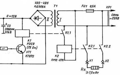
Figure 6
Thermostat power supply
The power supply unit of the device is unstabilized, and since the temperature regulator itself (one microcircuit and one transistor) consumes almost no power, any Chinese-made network adapter is suitable as a power source.
If you make a power supply, as shown in the diagram, then a small power transformer from a cassette recorder tape recorder or something else is quite suitable. The main thing is that the voltage on the secondary winding should not exceed 12..14V. With a lower voltage, the relay will not work, and with a higher voltage it can simply burn out.
If the output voltage of the transformer is in the range of 17 ... 19V, then here you can not do without a stabilizer. This should not be scary, because modern integrated stabilizers have only 3 outputs, it is not so difficult to solder them.
Load on
The open transistor VT1 turns on the relay K1, which by its contact K1.1 turns on the magnetic starter K2. The contacts of the magnetic starter K2.1 and K2.2 connect the heater to the network. It should be noted that the heater turns on immediately with two contacts. This solution ensures that when the starter is disconnected, the phase will not remain on the load, unless, of course, everything is in order.
Since the cellar is humid, sometimes very damp, in terms of electrical safety is very dangerous, it is best to connect the entire device using RCD according to all requirements for modern wiring. The rules of the electrical wiring in the basement can be found in this article.
What should be the heater
Schemes of temperature regulators for the cellar published a lot.Once they were published by the Modelist-Kostruktor magazine and other print publications, but now all this abundance has migrated to the Internet. These articles provide recommendations on how the heater should be.
Someone offers ordinary hundred-watt incandescent lamps, tubular heaters of the TEN brand, oil radiators (it is possible even with a faulty bimetallic regulator). It is also proposed to use domestic heaters with a built-in fan. The main thing is that there is no direct access to live parts. Therefore, old electric stoves with an open spiral and homemade goat type heaters Do not use in any case.
Check installation first
If the device is assembled without errors from serviceable parts, then special adjustment is not required. But in any case, before the first start-up, it is imperative to check the installation quality: are there no soldering or vice versa closed tracks on the printed circuit board. And you must not forget to do these actions, just take it as a rule. This is especially true for structures connected to the electrical network.
Setting the thermostat
If the first inclusion of the structure occurred without smoke and explosions, then the only thing to do is set the reference voltage at the direct input of the comparator (pin 2), according to the desired temperature. To do this, you need to make several calculations.
Assume that the temperature in the cellar should be maintained at +2 degrees Celsius. Then first we translate it into Kelvin degrees, then we multiply the result by 0.010V, the result is a reference voltage, it is also the temperature setting.
(273.15 + 2) * 0.010 = 2.7515 (V)
If it is assumed that the thermostat must maintain a temperature of, for example, +4 degrees, then the following result will be obtained: (273.15 + 4) * 0.010 = 2.7715 (V)
Boris Aladyshkin
See also at e.imadeself.com
: