Categories: Featured Articles » Practical Electronics
Number of views: 78408
Comments on the article: 3
Timer 555. Voltage Converters
DC / DC Converter
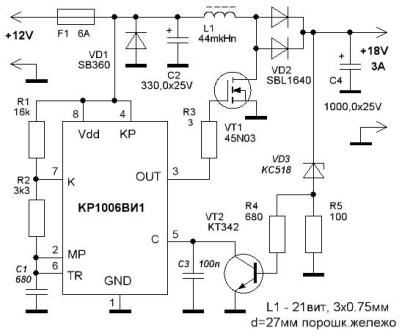
 Quite often in various schemes are required voltage converters. The most typical example is powering a device from a car battery. Typically, such voltage converters are push-pull based on various specialized microcircuits. But, if the power of the converter is small, it is quite possible to create one on the basis of the 555 timer (KR1006VI1). A diagram of one of the possible options is shown in Figure 1.
The circuit contains the familiar previous articles on timer 555 self-oscillating multivibrator, the output of which (pin 3) is connected to the gate of a powerful field-effect transistor VT1. A choke L1 is connected to the drain of the same transistor.
When the power is turned on, the generator begins to produce rectangular pulses. Therefore, self-induction EMF pulses appear on the inductor L1, which are rectified by the diode assembly VD2, and charge the output filter capacitor C4 to the voltage specified by the zener diode VD3.
The stabilization device is a threshold device, almost a comparator, with a threshold set by the Zener diode VD3.
The stabilization device works as follows: as soon as the voltage on the capacitor C4 exceeds the stabilization voltage of the zener diode and the base-emitter transition of the VT2 transistor, the latter opens, which will lead to a decrease in the pulse duration at the timer output and a decrease in the voltage on the capacitor C4. Further, the entire cycle is repeated.

Figure 1. Scheme of the DC / DC converter on the 555 timer
The voltage at the output of the device depends entirely on the stabilization voltage of the zener diode, and can reach up to 40 volts. In the considered circuit, the output voltage is higher than that of the power source and is 18V. If you need to get, for example, 9 or 5V, just apply a zener diode to the specified stabilization voltage. All other parts will not require replacement.
555 micropower converter
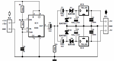
Often in different equipment required low power bipolar power. An example is the case when you need to power just one operational amplifier. A diagram of such a converter is shown in Figure 2.

Figure 2. Scheme of a micropower voltage converter on the 555 timer
Of course, the modern elemental base has specialized converter chipsthat you can buy on the radio market. But often in such cases it is necessary to say: “Where are we, and where is the radio market?”, And the high cost of specialized microcircuits sometimes disheartens. Therefore, it is necessary to get out of the situation using the parts already at hand.
The principle to do not from what is needed, but from what is, often gives excellent results, in any case, saving time, which is always not enough.
Here and here our old friend will help - multivibrator. With the details of the details indicated on the diagram, the operating frequency of the generator is about 160KHz. The voltage pulses from its output through the isolation capacitor C4 go directly to two rectifiers, assembled according to the voltage doubling circuit.
The output voltage is stabilized by integrated stabilizers. For positive voltage it is 78L05, for negative 79L05. Thus, a bipolar stabilized converter with a stabilization voltage of ± 5V is obtained.
The input voltage of the converter is in the range of 11 ... 18V. With a 12V input voltage, the output current is about 50mA. With these parameters, it is quite possible to power a couple of op-amps.
Voltage to Frequency Converter (VLF)
In some cases, such a conversion is required. Such schemes are quite complex, contain a large number of parts, are moody in commissioning. There are of course specialized integrated IFsbut they are quite expensive, and besides, they are not always at hand. Therefore, often in such a situation, the widespread 555 timer.
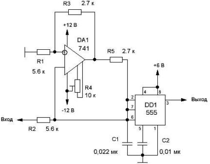
The IFF circuit for timer 555 is shown in Figure 3.

Figure 3. VLF circuit on timer 555
The VLF is based on the same multivibrator, but if in the classical circuit the charge of the timing capacitor C1 is carried out through a resistor, then in this case the capacitor is charged through a controlled current source, which is made using an operational amplifier. The diagram shows an op amp of type 741, the domestic counterpart of which is 140UD7.
The current source is designed so that the output current linearly depends on the input voltage and is almost independent of the load resistance. When using a current source, the capacitor charges linearly and not exponentially, as is the case with a resistor.
Upon reaching a certain voltage, namely 2 / 3U, (threshold of operation of the upper comparator), the capacitor is discharged, forming a voltage pulse at the output of the timer. After that, a new charge begins - the discharge of the capacitor. Therefore, the frequency of the output voltage at the output of the IF is linearly dependent on the input voltage.
If a constant voltage is applied to the input of the device within 0.5 ... 7V, the output frequency changes in the range of 1.8 ... 24KHz, which corresponds to a steepness of conversion of about 3.4KHz / V.
Short pulses at the output of the device have a negative polarity. Moreover, the conversion error does not exceed 3.4%. Such a converter can be used, for example, in temperature meterswhen you want to digitize information from an analog sensor.
CONTINUED ARTICLE: PWM - 555 engine speed controllers
Boris Aladyshkin, https://e.imadeself.com/en
See also at e.imadeself.com
:
