Categories: Featured Articles » Practical Electronics
Number of views: 308,394
Comments on the article: 9
PWM - 555 engine speed controllers
 The 555 timer is widely used in control devices, for example, in PWM - speed regulators of DC motors.
Everyone who has ever used a cordless screwdriver must have heard a squeak coming from inside. This is whistled by the motor windings under the influence of the pulse voltage generated by the PWM system.
Another way to regulate the speed of the engine connected to the battery is simply indecent, although it is possible. For example, simply connect a powerful rheostat in series with the engine, or use an adjustable linear voltage regulator with a large radiator.
Option PWM - controller based on 555 timer shown in figure 1.
The circuit is quite simple and everything is based on a multivibrator, although converted into a pulse generator with an adjustable duty cycle, which depends on the ratio of the charge speed and the discharge of capacitor C1.
The capacitor charges through the circuit: + 12V, R1, D1, the left side of the resistor P1, C1, GND. And the capacitor is discharged along the circuit: the top plate C1, the right side of the resistor P1, the diode D2, pin 7 of the timer, the bottom plate C1. By rotating the slider of the resistor P1, you can change the ratio of the resistances of its left and right parts, and therefore the charge and discharge time of the capacitor C1, and as a consequence the duty cycle of the pulses.

Figure 1. Scheme of the PWM controller on the 555 timer
This scheme is so popular that it is already available as a set, which is shown in the following figures.

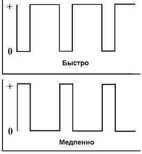
Figure 2. Schematic diagram of a set of PWM - controller.
Timing diagrams are also shown here, but, unfortunately, the details of the parts are not shown. They can be seen in Figure 1, for which he, in fact, is shown here. Instead bipolar transistor TR1 without altering the circuit, you can apply a powerful field, which will increase the load power.
By the way, another element appeared on this circuit - the D4 diode. Its purpose is to prevent the discharge of the capacitor C1 through the power source and the load - the motor. This ensures stabilization of the PWM frequency.
By the way, with the help of such schemes it is possible to control not only the speed of the DC motor, but also just the active load - an incandescent lamp or some kind of heating element.

Figure 3. The printed circuit board of the PWM controller kit.
If you make a little work, it is quite possible to recreate one using one of the programs for drawing printed circuit boards. Although, given the scarcity of details, one instance will be easier to assemble by surface mounting.

Figure 4. Appearance of a set of PWM regulator.
True, the already compiled corporate set looks pretty pretty.
Here, maybe someone will ask a question: “The load in these regulators is connected between + 12V and the collector of the output transistor. And what about, for example, in a car, because everything is already connected to the mass, body, and car there? ”
Yes, you can’t argue against the mass, here you can only recommend moving the transistor switch to the gap of the “positive” wire. A possible variant of such a scheme is shown in Figure 5.

Figure 5
Figure 6 shows a separate output stage. on the MOSFET transistor. The drain of the transistor is connected to a + 12V battery, the shutter just “hangs” in the air (which is not recommended), the load is included in the source circuit, in our case a light bulb. This picture is just shown to explain how the MOSFET transistor works.

Figure 6
In order to open the MOSFET transistor, it is enough to apply a positive voltage to the gate relative to the source. In this case, the bulb will light up completely and will light until the transistor is closed.
In this figure, it is easiest to close the transistor by shorting the gate with the source.And such a manual closure for testing the transistor is quite suitable, but in a real circuit, the more pulsed it will be necessary to add a few more details, as shown in Figure 5.
As mentioned above, an additional voltage source is required to open the MOSFET transistor. In our circuit, its role is played by the capacitor C1, which is charged through the + 12V, R2, VD1, C1, LA1, GND circuit.
To open the transistor VT1, it is necessary to apply a positive voltage from the charged capacitor C2 to its gate. It is obvious that this will happen only when the transistor VT2 is open. And this is possible only if the transistor of the optocoupler OP1 is closed. Then the positive voltage from the positive side of the capacitor C2 through the resistors R4 and R1 will open the transistor VT2.
At this moment, the PWM input signal should be low and the optocoupler LED shunted (this inclusion of LEDs is often called inverse), therefore, the optocoupler LED is off and the transistor is closed.
To close the output transistor, you must connect its gate to the source. In our circuit, this will happen when the transistor VT3 opens, and this requires that the output transistor of the optocoupler OP1 be open.
The PWM signal at this time is high, so the LED does not shunt and emits the infrared rays laid to it, the optocoupler transistor OP1 is open, which as a result leads to the disconnection of the load - the bulb.
As one of the applications of such a scheme in a car, these are daytime running lights. In this case, motorists claim to use high-beam lamps, included in the full light. Most often, these designs on microcontroller, the Internet is full of them, but it's easier to do on a timer NE555.
CONTINUED ARTICLE: Drivers for MOSFET transistors on a 555 timer
Boris Aladyshkin
See also at e.imadeself.com
: