Categories: Featured Articles » Practical Electronics
Number of views: 41249
Comments on the article: 1
555 Integrated Timer. Traveling the Data sheet
 Once, just some twenty years ago, almost all electronic equipment, both domestic and industrial, was domestically produced. Accordingly, the entire elemental base - transistors, microcircuits, diodes, resistors, was used domestic.
To understand this, albeit not very large by modern standards, reference books were issued. This literature was so scarce that, in current terms, it should be called a bestseller: in bookstores, all literature on electronics was sold out instantly. The purchasers of these books were mainly radio amateurs and repair engineers.
Like in Yandex. There is everything
Currently, all electronics are developed and manufactured abroad, so the entire elemental base is also “from there”. This is noticeable already at the stage of acquiring radio components on radio markets and in online stores. If you are looking for, for example, KR1006VI1, then helpful sellers will certainly offer you NE555. You can find a lot of similar examples. This state of affairs is simply pleasing, because it’s a sin to hide, in Soviet times, radio components simply “dragged” from the enterprises, but at the same time not everything that was wanted was found.
Naturally, paper directories for imported parts cannot be found, since they simply are not issued. But firms - manufacturers for each transistor, diode or microcircuit in electronic format, most often in the form of * .pdf files, release technical documentation - Data sheetwhich can always be found on the Internet.
Now you don’t have to leaf through a thousand-page manual to find the technical characteristics of a single transistor or diode. This amount of information fits on just one or two pages. True, it should be noted that if this Data sheet is for something more complicated, for example, for a microcontroller, then the description may take more than a dozen, or even hundreds of pages.
555 Integrated Timer Data Sheet
In electronic format is a file NE555.pdf, with a volume of about 600 kilobytes. In this case, you should pay attention to this detail. Documentation Data sheet, like the 555 timers themselves, is produced by many companies. Timers remain timers, nothing changes inside or outside them. But the volume of Data sheet files can vary from a hundred with a small kilobyte to almost seven hundred. It is about 25 pages.
This difference is due to the fact that in some descriptions you can find only electrical parameters, the pinout, the name of the signals and the internal circuit. And in other, more voluminous, there are also different switching schemes, calculation formulas and much more. Therefore, ceteris paribus, you should watch more voluminous * .pdf files. Next, several schemes from the Data sheet NE555.pdf will be considered.
Multivibrator from Data sheet
In the previous article "Designs on the integral timer 555" Figure 9 was a diagram of a self-oscillating multivibrator. This circuit does not use pin 7, which is specifically designed for the discharge of a time-setting capacitor, and the capacitor is charged and discharged through resistor R1. Therefore, the output pulses of this generator can only be pulses of the form of a meander. The duty cycle of such pulses is 2.
In order to obtain pulses of any required duty cycle, manufacturers recommend a slightly different circuit, shown in Figure 1.
The footnote to the figure says that the 5 CONT pin should be connected to a common wire through a small capacitor to prevent interference. About this conclusion will be described below.

Picture 1.
And Figure 2 shows the timing diagrams.

Figure 2
When the power is turned on, the capacitor C is discharged, so the TRIG pin 2 is low, which causes the output OUT (pin 3) to be set high.Capacitor C starts charging through the resistors (Ra + Rb) until the voltage across it reaches the upper threshold of the timer (0.67 * Vcc). The charge time will be tH = 0.693 * (RA + RB) * C.
In this way, the pulse duration is formed.
After this time, the timer output switches to low level, and the capacitor C is discharged through the resistor RB and a special output 7 DISCH (discharge). The discharge continues until the voltage across the capacitor drops to (0.33 * V), the response threshold comparator TRIG. The output of the timer is set high, and the cycle starts again. The discharge time is tL = 0.693 * (RB) * C. This will be the pause time.
The pulse repetition period is equal to the sum of the pulse and pause period = tH + tL + 0.693 * (RA + 2RB) * C, and the pulse repetition rate will be frequency ≈ 1.44 / ((RA + 2RB) * C).
Figure 3 shows a nomogram taken from a datasheet. It allows you to at least approximately determine the frequency of the pulses with any combination of a time-setting capacitor and resistors. More precisely, the frequency is selected during calculations, and later during tuning. After all, it is no secret to anyone that many formulas in electronics give approximate results.
When using the nomogram, the reverse is also quite possible, namely, to select the parameters of the RC chain at a given frequency.
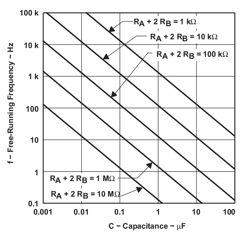
Figure 3
You should pay attention to such a detail: in none of the formulas above, there is a supply voltage. Consequently, the frequency of oscillations, and their duty cycle, in no way depend on nutrition. These values are set only by the parameters of the RC chain. The stability of the pulse frequency at the output of the timer also depends on the stability of these parameters.
Mysterious conclusion 5 CONT
CONT stands for CONTROL Control. It is here that the control voltage is applied, sometimes it is called modulating. With it, you can change the fixed values of the thresholds of the comparators, which makes it possible to change the charge time - discharge of the time-setting capacitor. This control allows you to create generators with PWM and time-pulse modulation of the signal. The PWM modulator circuit is shown in Figure 4, and its timing diagram in Figure 5.
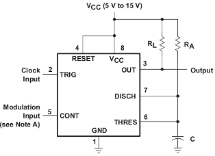
Figure 4
If you look closely at the circuit, then we can say that this is a familiar one-shot. His description was given in the article. "Designs on the integral timer 555". Only the 5 CONT pin is not used in the single-oscillator circuit, it is simply recommended to “ground” it through the capacitor shown by the dashed line. The timing diagrams shown in Figure 5 allow us to draw the following conclusions:
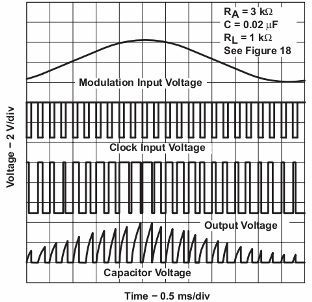
Figure 5
By itself, the pulse modulator does not produce, i.e. is not a generator.
External pulses are fed to its input, in this case with a constant frequency and duty cycle.
An alternating modulating voltage is applied to the control input CONT, under the action of which the thresholds of the input comparators are changed. The modulating voltage can be supplied either directly or through an isolation capacitor, as described in the note to the circuit in the datasheet.
The thresholds for the operation of the comparators determine the voltage of the charge — the discharge of the time-setting capacitor C. What is obtained from this is clearly shown in the lower diagram in Figure 5.
Pulsed oscillator
Its circuit is shown in Figure 6.
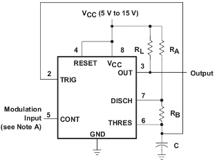
Figure 6
The circuit exactly repeats the multivibrator circuit shown in Figure 1, only it uses pin 5 CONT, to which a triangular-shaped control voltage is applied. The timing diagram of this generator is shown in Figure 7.
It should be noted that all time charts show horizontal scan times and the sensitivity of the vertical deflection channel. That is, before us is not just a freehand drawing, but real oscillograms. Therefore, they can be used to determine the amplitude of the modulating voltages, as well as the period and frequency of the input and output pulses.
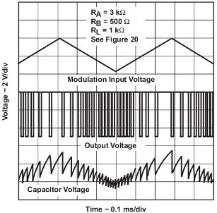
Figure 7
The voltage on the capacitor, or rather its envelope, exactly repeats the shape of the modulating signal, and the frequency of the output pulses varies depending on the modulating voltage. With a minimum modulating voltage, the generator output frequency is maximum. As this voltage increases, the output frequency decreases and reaches a minimum when the modulating voltage reaches a maximum.
When the modulating voltage, having passed the maximum, begins to fall, the output frequency of the generator begins to increase, - the cycle repeats again. The amplitude of the charge - discharge of the time-varying capacitor also changes under the influence of modulating voltage.
In addition to the circuits considered, the Data sheet also considers circuits of the already mentioned one-shot, pulse loss detector, frequency divider, as well as the sequence timer circuit shown in Figure 8.
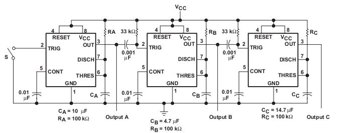
Figure 8
The logic of the timer is simple: when you press the S button, timer A starts and a high level voltage appears at the output of Output A, which, after the shutter speed set by the RA * CA timing circuit, goes to a low level. The negative difference of this pulse through the differentiating circuit 0.001uF * 33KΩ is fed to the TRIG input of the next one-shot and starts it.
At the output of the second one-shot set a high level. At the end of the time delay, the second one-shot starts the third. In principle, it is possible to increase this serial chain of one-shots to infinity. The timing diagram for the three cells is shown in Figure 9.

Figure 9
Look at the datasheet!
Here is such useful information about the work, in this case, the integral timer 555 can be gleaned by studying the datasheet. And often in many electronic forums you have to see such dialogs: help, pliz, assembled the circuit, but turning it on - it doesn’t work. And sometimes in response it sounds, they say, look datasheet!
Continuation of the article:Timer 555. Voltage Converters
See also at e.imadeself.com
: