Categories: Practical Electronics, Repair of household appliances
Number of views: 109075
Comments on the article: 31
How to repair a Chinese chandelier - the story of one repair
 In the article "How to control a chandelier in two wires" various schemes were considered, allowing switching several groups of lamps. The operation algorithm for all circuits is the same: with a short click of the switch, the first group lights up, with the second second, with the third click both groups at once. To turn off the chandelier, switch the switch, as usual, to the open position.
All the circuits considered at different times were developed by radio amateurs. In Chinese-made chandeliers, such devices are already installed, and in addition to them there are some additional lighting and even sometimes sound effects. My colleague at work was engaged in the repair of one of these devices: until you are busy repairing production equipment, you can work hard for yourself. And the defect of the mentioned device was like this - no matter how you click the switch, nothing turns on. Still managed to repair the circuit, but in a somewhat unusual way. Moreover, the defect itself was not understood by us. But first things first.
In appearance, the device is quite simple. There are two relays, a microcircuit, and several parts on the board that are slightly larger than the matchbox. The appearance of the board is shown in Figure 1.

Figure 1. The appearance of the board of the Chinese chandelier
Chinese DATASHEET
It was natural to assume that all the logic of work is hidden in the HL2609 chip. Searching for familiar sites with datasheets yielded nothing: we could not find the chip anywhere. But as a result of searches in Google and Yandex, it was still possible to find a mysterious stranger. True, the description was in Chinese, which was actually expected.
It was not possible to download it, as usual, in * .pdf format, so I had to be content with screenshots - screenshots. In total, there were three such screenshots, the first of which is shown in Figure 2.

Figure 2. Pinout and operating modes of the HL2609 chip.
If you do not pay attention to the hieroglyphs, then from this figure you can draw the following information.
Firstly, we have an HL2609 chip in the DIP-8 package. Secondly, this is a microchip of the CMOS structure (in the Russian version it is also a CMOS), is operable in the range of supply voltages 2 ... 16V, with a maximum output current of up to 70mA. It also shows the pinout (a more modern, somewhat slang term - pinout) of the microcircuit.
Power is supplied between 1 and 5 pins, the load (L1, L2) is connected to pins 7 and 8, pins 2 and 6, designated as NC (No Connect) inside the microcircuit are not connected anywhere.
Pin 3, denoted as R, is the reset of the microcircuit to its initial state when it is first turned on, and pin 4 of CLK is a clock pulse that changes the state of the microcircuit during subsequent short-term clicks of the switch.
Figure 3 in the bottom table shows the logic of the microcircuit (truth table). She does not need detailed explanations.

Figure 3. The logic of the HL2609 chip.
On the same page of the Chinese datasheet is a diagram of the entire device, apparently, as a typical switching scheme. It is shown in Figure 4. Unfortunately, the internal structure of the microcircuit is not shown, but how could it help during the repair?

Figure 4. Typical HL2609 circuitry.
How it should work
Details on the diagram, as well as on the board itself, do not have standard designations, such as R1, R2, C1, etc. Therefore, to simplify the description, in the diagram this numbering had to be done additionally. Part numbers are shown in Figure 4.
The entire circuit is powered by a transformerless rectifier VD1, made according to a bridge circuit with blanking capacitor C1.When you turn on the device for the first time (1 column of the truth table), until capacitor C2 is charged, capacitor C3 has a low voltage, which resets the microcircuit to its initial state, both relays are off, the lamps naturally do not light. Further, the capacitor C3 is charged to a high level and is not affected by the further operation of the circuit.
At the same time, the capacitor C5 is charged, which provides power to the chip for a short click of the switch to switch groups of lamps. With each click, a clock pulse is generated on the capacitor C4, and the relay switches according to the truth table shown in Figure 3.
Since the capacitor C2 does not have time to completely discharge during a short click, the reset pulse on the capacitor C3 is not formed and the device does not return to its original state. The chandelier is turned off as usual, which corresponds to the last column of the truth table.
Everything seems to be simple, clear and understandable, but, as the classic used to say ...
“And turn it on - does not work!”
The scheme of the device and the logic of its operation are simple and clear, it would seem that there is simply nothing to not work in it. And yet…
External manifestation of the defect - not a single group of lamps is turned on. Checking parts, diodes and resistors, a multimeter did not find faulty parts. Capacitors were checked simply by replacement method. What was the conclusion from here? The chip is to blame.
When examining the circuit, it turned out that the relays seemed to be trying to turn on, and the switching sequence completely corresponded to the truth table shown in Figure 3. But switching on did not occur completely: on terminals 7 and 8, the voltage dropped only to 5 volts. But with fully open output transistors, the voltage at these terminals should be no more than 0.5V.
By the way, the voltage across the capacitor C2 also "sagged" to 5V. An increase in the capacity of the quenching capacitor C1 also did not lead to the elimination of the defect. Also, a diode bridge was checked by replacement. No positive effect was achieved.
Research has been continued. Instead of a relay, LEDs were connected, of course, with limiting resistors. When the switch clicks, the LEDs light up and go out in the required sequence shown in the truth table. That seems to be the way to solve the problem! It is necessary to put an optocoupler with a transistor, such a kind of amplifier, which will control the operation of the relay. These experiments are shown in Figure 5.
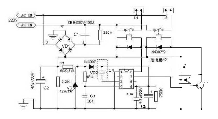
Figure 5
The reasoning was as follows. A faulty microcircuit cannot turn on the relay, and the optocoupler LED should offload the output stage of the microcircuit. The transistor at the output of the optocoupler will easily and unconditionally turn on the relay. But our surprise knew no bounds when this revision still did not turn on the relay. It would seem that the experiments have reached an impasse and further continuation does not make sense.
The problem was solved by a completely different method. The circuit was restored to its original state, and an additional source was connected in parallel to the capacitor C2, just a suitable 12V transformer with a rectifier bridge.
After such an addition, the circuit worked, as expected, the entire switching algorithm is fully implemented. Still, the problem lies inside the chip, but it is unlikely to buy one. Therefore, here you can only repeat the hackneyed phrase that all means are good for achieving the result. The additional connections made are shown in Figure 6.
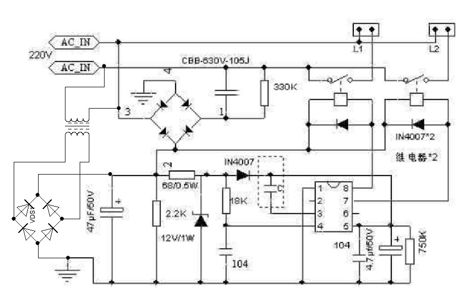
Figure 6
Boris Aladyshkin
See also at e.imadeself.com
: