Categories: Featured Articles » Practical Electronics
Number of views: 51598
Comments on the article: 6
Two-wire chandelier control circuits using semiconductors
The first part of the article: How to control a chandelier in two wires. Relay circuits.
 One good engineer, an electronics engineer, said that if, supposedly, there is a relay in the circuit, then it needs to be improved. And one cannot disagree with this: the contact actuation resource of the relay contacts is only a few hundred, maybe thousands of times, while a transistor operating at a frequency of at least 1 KHz makes 1000 switches every second.
Field Effect Transistor Circuit
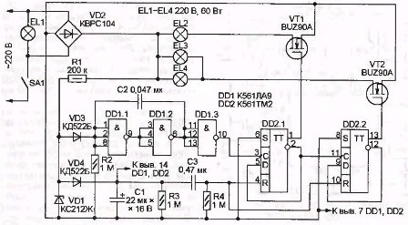
This scheme was proposed in the journal "Radio" No. 9 of 2006. It is shown in Figure 1.
The algorithm of the circuit is the same as the previous two: with each short-term click of the switch, a new group of lamps is connected. Only in those schemes there is one group, and in this whole two.
It is easy to see that the basis of the circuit is a two-digit counter made on the K561TM2 chip, containing 2 D - flip-flops in one housing. These triggers contain an ordinary two-digit binary counter, which can be counted according to the algorithm 00b, 01b, 10b, 11b, and again in the same order 00b, 01b, 10b, 11b ... The letter “b” indicates that the numbers are in the binary system numbering. The low-order bit in these numbers corresponds to the direct output of the trigger DD2.1, and the senior one to the direct output of DD2.2. Each unit in these numbers indicates that the corresponding transistor is open and the corresponding group of lamps is connected.
Thus, the following algorithm for turning on the lamps is obtained. Lamp EL1 shines as soon as switch SA1 closes. When the switch is pressed briefly, the lamps will light up in the following combinations: EL1; (EL1 & EL2); (EL1 & EL3 & EL4); (EL1 & EL2 & EL3 & EL4).
In order to carry out the switching according to the indicated algorithm, it is necessary to apply counting pulses to the input C of the least significant bit of the counter DD2.1 at the moment of each click of the switch SA1.
Figure 1. The control circuit of the chandelier on field-effect transistors
Counter management
It is carried out by two impulses. The first of them is the counter reset pulse, and the second is the counting pulse switching the lamps.
Counter reset pulse
When you turn on the device after a long shutdown (at least 15 seconds) electrolytic capacitor C1 completely discharged. When the switch SA1 is closed, the pulsating voltage from the rectifier bridge VD2 with a frequency of 100 Hz through the resistor R1 generates voltage pulses limited by the Zener diode VD1 at 12V. With these pulses, an electrolytic capacitor C1 starts charging through the decoupling diode VD4. At this moment, the differential chain C3, R4 generates a high-level pulse at the R - inputs of the triggers DD2.1, DD2.2, and the counter is reset to state 00. Transistors VT1, VT2 are closed, so when you first turn on the chandelier, the lamps EL2 ... EL4 do not light. Only the EL lamp remains on, as it is switched on directly by the switch.
Counting pulses
Through the diode VD3, pulses generated by the Zener diode VD1 charge the capacitor C2 and maintain it in a charged state. Therefore, the output logical element DD1.3 low logic level.
When the circuit breaker SA1 is opened for a short time, the ripple voltage from the rectifier stops. Therefore, the capacitor C2 manages to discharge, which will take about 30ms, and a high logic level is set at the output of the DD1.3 element - a voltage drop is formed from a low level to a high one, or as it is often called the rising edge of the pulse. It is this rising front that sets the DD2.1 trigger to a single state, preparing to turn on the lamp.
If you look closely at the image in diagram D, a trigger, you can notice that its clocked input C begins with an inclined segment going from left - up - to right.This segment indicates that the trigger is triggered at input C along the rising edge of the pulse.
Here is the time to recall the electrolytic capacitor C1. Connected via a decoupling diode VD4, it can only be discharged through microcircuits DD1 and DD2, in other words, to maintain them in working condition for some time. The question is how long?
Chips of the K561 series can operate in the range of the supply voltage 3 ... 15V, and in the static mode, the current consumed by them is calculated in units of microamps. Therefore, in this design, a full discharge of the capacitor occurs no earlier than after 15 seconds and then, thanks to the resistor R3.
Since the capacitor C1 is almost not discharged, when the switch SA1 closes, a reset pulse is not generated by the chain C3, R4, so the counter remains in the state that it received after the next counting pulse. In turn, a counting pulse is generated at the moment of opening SA1, each time increasing the state of the counter by one. After closing SA1, the mains voltage is applied to the circuit and the lamp EL1 and lamps EL2 ... EL4 light up in accordance with the counter status.
With the modern development of semiconductor technologies, key (switching) cascades performed on field effect transistors (MOSFET). Making such keys on bipolar transistors is now considered simply indecent. In this circuit, these are transistors of the BUZ90A type, which allow you to control incandescent lamps with a power of up to 60 W, and when using energy-saving lamps, this power is more than enough.
Another option scheme
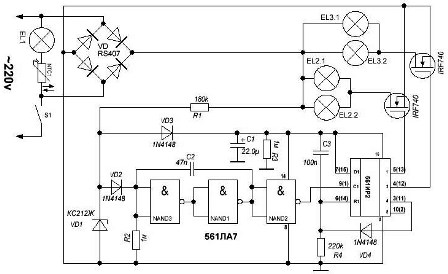
Figure 2 shows a possible variant of the scheme just considered.
Figure 2. Control circuit of 5 (3) -x lamp chandelier
Instead of a counter on D-flip-flops, the shift register K561IR2 is used in the circuit. In one housing of the microcircuit contains 2 such registers. Only one is used in the circuit; its conclusions in the circuit are shown in brackets. Such a replacement allowed to slightly reduce the number of printed conductors on the board, or the author simply did not have another chip. But in general, outwardly, nothing has changed in the operation of the circuit.
The logic of the shift register is very simple. Each pulse arriving at input C transfers the contents of input D to output 1, and also performs a shift of information according to the 1-2-4-8 algorithm.
Since in this circuit the input D is simply soldered to the + power supply of the microcircuit (constant “log. Unit”), units will appear at the outputs at each shear pulse at input C. Thus, the ignition of the lamps occurs in the sequence: 0000, 0001, 0011, 0000. If you do not forget about the lamp EL1, then with it the switching sequence will be as follows: EL1; (EL1 & EL2); (EL1 & EL2 & EL3).
The first combination 0000 will appear when the chandelier is initially turned on under the influence of a reset pulse generated by the differential chain C3, R4, as in the previous scheme. The last zero combination will also appear due to the reset of the register, but only this time the reset signal will come through the diode VD4, as soon as output 4 appears the signal logical 1, i.e. at the fourth click of the switch.
The remaining elements of the circuit are already familiar to us from the description of the previous one. A shear pulse shaper is assembled on the K561LA7 chip (before it was a three-input LA9, also turned on by an inverter), and the electrolytic capacitor C1 acts as a power source for the chips during a short click of the switch. The output keys are all the same MOSFETs, though a different type of IRF740, which generally does not change anything.
Thyristor control circuit
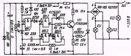
For some reason, the previous circuits switched the lamps using field-effect transistors, although thyristors and triacs. A circuit using a thyristor is shown in Figure 3.
Figure 3. The control circuit of the chandelier on thyristors
As in previous schemes, one EL3 lamp turns on simply when the SA1 switch closes. Lamp group EL1, EL2 turns on when the SA1 switch is clicked again. The scheme works as follows.
When SA1 is first closed, the EL3 lamp lights up, and at the same time, the pulsating voltage from the rectifier bridge through the resistor R4 is supplied to a voltage stabilizer made on the Zener diode VD1 and capacitor C1, which is quickly charged to the stabilization voltage of the zener diode. This voltage is used to power the DD1 chip.
At the same time, the electrolytic capacitor C2 starts charging through the resistor R2, and not very quickly. At this time, the output of the element DD1.1 is a high level, which charges the capacitor C3, so that on its right-hand side according to the circuit, the plus.
As soon as the charge of the capacitor C3 reaches the level of a logical unit, a low level will appear at the output of the element DD1.1, but at the inputs of the elements DD1.2 DD1.3, due to the charged capacitor C3 and the decoupling diode VD4, a high level will remain. Therefore, at the outputs 4 and 10 of the element DD1, a low level is held, which keeps the transistor VT1 closed. Thyristor VS1 is also closed, so the lamps do not light.
With a short click on the switch SA1, the capacitor C1 discharges quickly enough, thereby disconnecting the microcircuit. The discharge constant of the capacitor C2 is much higher, with the ratings indicated on the circuit for at least 1 second. Therefore, the capacitor C3 will quickly recharge in the opposite direction - plus will be on its left lining according to the scheme.
If in time less than one second it is time to turn on the chandelier again, then at the input of the element DD1.1 due to capacitor C1 that has not had time to discharge, a high voltage level will already be present, and at the inputs of the elements DD1.2, DD1.3 low, set by the direction of the charge of the capacitor C3. At the outputs 4 and 10 of the element DD1, a high level is set, which opens the transistor VT1, and that in turn is the thyristor VS1, igniting the lamps EL1, EL2. In the future, this state of the element DD1 is maintained by feedback through the resistor R3.
Microcontroller control of a chandelier
Schemes on microcontrollers Not without reason are considered quite simple in circuit design. By adding a small number of attachments you can get a very functional device. True, the price paid for such circuit simplicity is writing programs without which the microcontroller, even a very powerful one, is just a piece of iron. But with a good program, this piece of iron turns in some cases into a work of art.
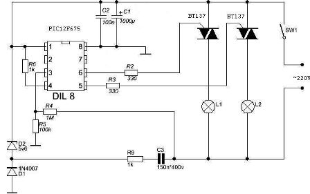
The control circuit of the chandelier on the microcontroller is shown in Figure 4.
Figure 4. The control circuit of the chandelier on the microcontroller
Like all the previous ones, the circuit is controlled by only one network switch SW1. The clicks of the switch allow not only to select the number of lamps turned on, but also to turn them on smoothly, to set the desired brightness of the glow. In addition, it allows you to simulate the presence of people in the house - turn on and off the lighting according to a certain algorithm. Such a simple security device.
Addition to the article: How to repair a Chinese chandelier - the story of one repair.
See also at e.imadeself.com
:

