Categories: Featured Articles » Practical Electronics
Number of views: 34059
Comments on the article: 4
How to control a chandelier in two wires. Relay circuits
 Dangers and hardships await a person always and everywhere, well, if not danger, then minor troubles and inconveniences are frequent guests, even in their own apartment.
A simple example. Your wife bought you a chandelier as a birthday present (last year you gave her a screwdriver or a drill to her), and offers to hang her in the bedroom, where so many years lonely and faithfully served her "Ilyich’s bulb". Perhaps even without a lampshade or shade.
A chandelier of three or even five lamps shines with beautiful glass and metal, and three, or maybe all four wires, stick out invitingly from it. What is called a transparent hint to replace the wiring in this room. After all, only two wires came up to a single lamp, and a single switch is still hanging on the wall (see, How to connect a chandelier to a switch) It is simply uneconomical to light five lamps at once, and it is not always convenient, for example, when watching TV. After all, as some humorist seems to say, “So that there are no scandals in the family, there must be at least two television sets in the house.”
But to open the hidden wiring from behind one chandelier, even if it’s gifted, I absolutely do not want to. This problem has already been solved by several generations of amateur radio enthusiasts and electricians. It was created and tested in the work of many different circuits, from just relay, to the most modern with microcontroller control. After all, it is much easier to assemble a simple device and hide it in the chandelier than to repair the apartment.
On the topic of the microcontroller inside the chandelier can be read on the forum "Radiokota". The guys write very instructive and interesting: one offers just to extend an additional wire on the ceiling, while the others advocate the use of a microcontroller or something else, but hidden in the chandelier itself. They are so and so, and that one, the first, again for his own. There’s a direct tug of war.
This article only discusses devices that are controlled by a network switch, although there are with remote control. For this purpose, it is possible to use a television remote control or even use a wireless Chinese radio call with some modifications.
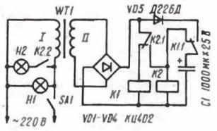
One of the first chandelier control circuits published in 1984 in Radio magazine is shown in Figure 1.

Figure 1. Two-wire chandelier control circuit
The circuit contains two relays and a transformer for their power supply. When the chandelier is turned on for the first time, along with the lamp H1, the transformer WT1 is turned on and the rectified voltage from the bridge VD1-VD4 turns on relay K1 via the normally closed contact of relay K2.1. Its normally open contact K1.1 connects to the rectifier via a decoupling diode VD5 electrolytic capacitor C1, which is charging. The lamp or group of lamps H1 is turned on.
To turn on the second lamp, you need to “lightly move your hand” flip a switch so light that the capacitor C1 does not have time to discharge. During this short click, relay K1 turns off and its normally closed contact K1.1 connects capacitor C1 to the coil of relay K2. Relay K2 is activated and can be held until capacitor C1 is discharged.
At this point, special attention should be paid, since the other devices described in the article also use the capacitor charge to power the device itself when the switch is clicked.
So, let's continue. The charged capacitor C1 holds the relay K2, which, with its normally open contact K2.1, switches to self-supply. Contact K2.2 will also be closed. If the switch SA1 at this time (until C1 is discharged) is closed again, then relay K2 will receive power from the rectifier, and lamp H2 will light up through contact K2.2, which has already been closed.The chandelier is turned off as usual.
Of course, with a modern element base, no one will do such a design, but still the principle of the circuit remains the same: until the capacitor has been discharged, you need to manage to turn on the second, and maybe the third lamp. Here is truly new - it is a well-forgotten old.
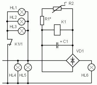
Another relay circuit is shown in Figure 2.
Figure 2. A simple two-wire chandelier relay control circuit
Unlike the previous one, it does not contain a transformer and is made on only one relay. Such a simplification of the circuit leads to a decrease in the dimensions of the device, but in return for this circuit requires some configuration efforts, as will be discussed below. The scheme works as follows.
When you first turn on the resistance thermistor R1 is large because it is in a cold state, more precisely at room temperature. Therefore, the voltage across the capacitor C1 does not slip, and it is enough for the relay K1 to operate. The relay is activated and its normally closed contact K1 / 1 will turn off the lamp group HL1 ... HL3. Therefore, when you turn on the device for the first time, this group of lamps will not light. After some time, the thermistor R1 warms up and its resistance decreases, due to which the voltage across the capacitor C1 drops.
Well, of course, not to the extent that the relay shuts down, but remains in the on state. This voltage should be slightly higher than the holding voltage of the relay, and slightly less than the voltage of its operation.
Here, as in the previous circuit, you should pay attention to the capacitor C1. When the switch is pressed for a short time, the relay is switched off, thereby connecting the lamp group HL1 ... HL3 via the normally closed contact K1 / 1. As soon as the switch is closed again, capacitor C1 will begin to charge. But the heated thermistor R1 with its small resistance will limit the voltage on the capacitor C1 to a level lower than the response voltage of the relay, so the relay will not turn on and the group of lamps HL1 ... HL3 will not turn off. Thus, all lamps will be turned on.
A few words about the details. The relay is suitable small-sized with a coil resistance of about 300 Ohms, a CT3-17 type thermistor with a resistance of 330 Ohms (at room temperature). In the absence of such a rating, you can use three such thermistors of 1 kOhm connected in parallel. Using a MLT-0.25 resistor R2, a resistance of several tens of Ohms, a voltage is selected in the mode of a heated thermistor R1, as indicated above. 50mkF * 25V electrolytic capacitor, better imported. Rectifier bridge KTs407A or assembled from discrete diodes, at least 1N4007. All parts are assembled by surface mounting and fit easily inside the chandelier.
This scheme is also not very modern, but if necessary, it can still be assembled - it really captivates with its simplicity, few details.
In the next article, we will consider several more chandelier control circuits using two wires, but this time it will be circuits using semiconductor devices and a microcontroller.
Continuation of the article: Two-wire chandelier control circuits using semiconductors
See also at e.imadeself.com
:

