Categories: Featured Articles » Electrician at home
Number of views: 59505
Comments on the article: 2
Wiring diagram in the garage: design and installation features
 People build buildings mainly for two purposes: for living or for solving technical issues. When creating the power supply system in these rooms, special attention is paid to the reliability and safe operation of the equipment.
In residential buildings, much attention is paid to the design of rooms. The electrical wiring in them is usually hidden inside the walls or created in an open way from exclusive expensive components that emphasize the individual style of the owner.
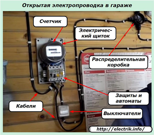
Buildings for technical needs, of which the garage belongs, are designed, as a rule, with a simple and open wiring diagram. Hiding it inside the walls does not make much sense: it’s easier to maintain and modify.
Types of voltage
For the vast majority of garages designed to contain one or two cars, single-phase power supply of 220 volts of industrial frequency is used. It is enough to create working lighting and a power outlet group for using electrified tools, chargers or launchers.
Three-phase voltage of 380 volts makes sense to connect for garages with a large number of cars, when there is a need to use electric boilers, machine tools with asynchronous electric motors, welding devices.
How to make a project
Future convenience of using electricity, its electricity consumption and the basics of security in the garage must be thought out in advance. The final decision is drawn up on paper. This will help to keep all ideas in mind, to calculate the necessary material resources, to assess their value.
To this end, a general plan of the garage plan is drawn up on a scale indicating the location of the main building elements and sketches of each wall, floor and ceiling.
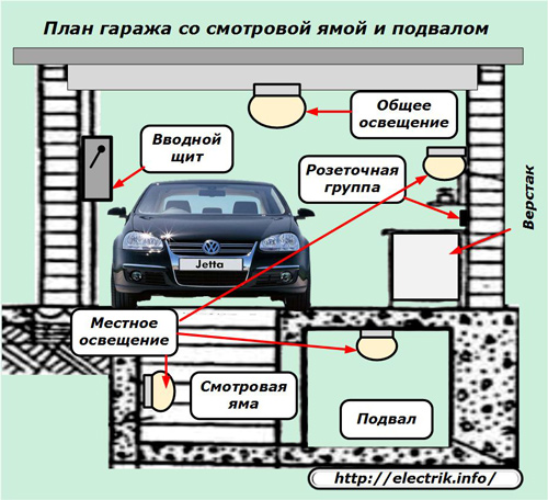
Then it is specified, it indicates:
-
sizes
-
installation location of the input shield;
-
coordinates of electrical points: lamps, switches and sockets.
The optimal routes for laying cables to electrical points are drawn from the input panel, taking into account the places of their passage through walls and other building structures. The sketch will help determine the number of junction boxes needed to connect switches to fixtures and sockets.
Then, the marking of electrical points is transferred to building structures, while simultaneously drawing routes of wires and cables.
The project should take into account the method of supplying electricity to opening shield from the supply line, taking into account the location of the garage itself. After all, it can be located in:
-
garage cooperative, which already has its own transformer substation with a branched power circuit;
-
near a private house or cottage with electrical power;
-
separately on the ground when you have to lay an overhead or cable power line.
These features can greatly affect the amount of power connection work.
At the project stage, safety issues related to lightning protection, emergency situations on the supply line, the need to use an individual building ground loop should be taken into account.
The composition of the wiring diagram in the garage
The main components:
-
input power distribution board;
-
metering devices, protections, automation;
-
cables and wires;
-
lighting devices and switches;
-
power outlet group.
In some cases, heating systems and other devices can be supplemented.
Power input
Electric energy is connected to the garage circuit using a special shield. In some cases, it is placed on the outside.
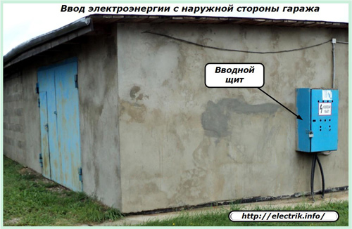
But, most often, the opening shield after the construction of the walls and the skeleton of the roof is installed inside the building at the beginning of construction.
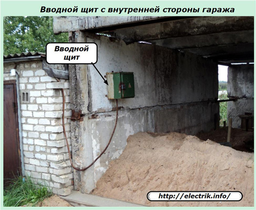
Its place is usually chosen near the front door or gate. It is more convenient and safer to turn off the power when leaving the garage when there is no need to use electricity.
The entry shield should be selected with the option of:
-
convenience of use;
-
restrictions on access by unauthorized persons to electrical devices;
-
the capacity of the necessary protections and switchgears.
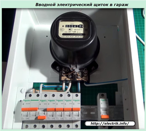
With the location of the garage in the general cooperative, there is a need pay for electricity on an individual meter. It is also located in the opening switchboard.
The final design of the input shield can be made independently of metal or buy a ready-made factory model in the store.
Protection devices
Inside the garage with a wiring diagram, various emergencies can occur. The consequences of their destructive activities are designed to prevent:
-
circuit breakers;
-
RCD and difavtomaty;
-
surge arresters;
-
voltage monitoring relay;
-
step-down isolation transformers.
Usually, garage owners use only automatic protection, abandoning other devices at their discretion. Such a decision is economically justified in many cases, but not in all ...
Circuit breakers
They are an indispensable element that prevents the effects of overloads and short circuits in a modern garage wiring diagram.
The introductory machine is located inside the introductory board in front of the electricity meter. If you use a simplified "grandfather" wiring diagram, consisting of a single light bulb located in the center of the ceiling and a single outlet, occasionally used to connect the carry, then in principle no more circuit breakers will be needed.
However, for modern conditions, this is clearly not enough. Given the increased number of electricity consumers: chargers and starting devices, electrified tools, heating and lighting systems, they are grouped as intended and powered by various circuit breakers selected according to load ratings. All these machines are located after the meter.
UZO and difavtomaty
Their purpose: to protect the garage owner from leakage currents arising through accidentally damaged circuit insulation.
This issue becomes particularly relevant when working in the inspection pit and basement of a garage with electrical appliances and equipment where increased humidity is created.
Surge arresters
If the garage is powered by an overhead power line, then during a thunderstorm period a lightning bolt can get into it. Its potential is partially extinguished by overhead line arresters, but the residual value is capable of arriving in the electrical wiring of the garage via a separate high-voltage pulse via power lines.
In this situation surge arresters they save the electric circuit from increased potential, divert it to the earth's circuit. They are installed after the introductory machine, but before the counter to ensure its protection.
To prevent such an accident, when surge arresters are not mounted in the input shield, experienced owners simply turn off the input circuit breakers or circuit breakers when a thunderstorm approaches. Is it convenient?
Voltage monitoring relay
In garage cooperatives, usually a lot of craftsmen and craftsmen gather, as well as those who look at their confident work and independently repeat their actions. Unqualified retry attempts often create malfunctions in the electrical circuit.
Zero-termination of a three-phase power circuit most often occurs in such situations. For consumers, it is manifested by increased voltage, from which light bulbs and working electric motors burn out.
The voltage control relay automatically de-energizes the circuit in case of such a malfunction, and prevents breakdowns of the connected equipment.
Modern residual current circuit breakers, difavtomata, surge arresters and ILV are produced in a compact modular design. They are mounted on din rail in the opening switchboard, take up little space inside it.
But even this advantage is ignored by many owners who create a fairly simple wiring diagram in a garage with one circuit breaker.
Step-down isolation transformers
Work in the inspection pit and basement is carried out in conditions of high humidity, it is dangerous. For electrical appliances, including lighting lamps, it is recommended to use a voltage reduced to 36 volts or less.
This function is assigned to isolation transformers. They increase electrical safety, exclude the possibility of electrical injuries.
Cables and wires
When choosing their design for a garage, you should pay attention to the properties of the insulating layer to withstand open fire, which can occur when a short circuit or ignition of flammable liquids.
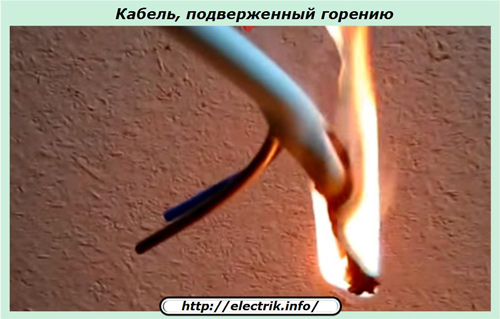
Cables subject to burning pose a serious danger. It must be laid in boxes or pipes that prevent the development of fire.
In order not to complicate the installation of electrical wiring in this way, it is easier to choose the brands of cables with a non-combustible insulation layer, which is marked with the addition of the index “ng” at the end of the type designation, for example, VVGng.

Also pay attention to:
-
the cross section of the core and its metal, affecting the choice of nominal loads (it is better to refuse aluminum);
-
dielectric strength of the insulation layer, its compliance with the class of applied voltage.
Lighting and switches
The garage lighting system is powered from individual circuit breakers. It is better to divide it into:
-
general, covering the entire area of the room with light;
-
local - for a specific workplace.
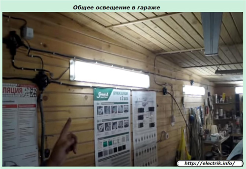
General lighting for the garage is quite well created by industrial fluorescent lamps, and the switch for them is conveniently placed near the entrance.
Local lighting can be divided by voltage:
-
regular 220 volts for normal use;
-
lowered through a separation transformer - in hazardous places.
Switches for local lighting are located near the workplace, but not inside the inspection pit and basement, but at the entrance.
Pay attention to the design of the lamp housing in the danger zone. According to the conditions of protection against penetration of foreign objects and moisture, it must meet the IP65 standard. Glasses are best protected with a metal mesh from accidental mechanical damage.
Power Outlet Group
Electrical consumption devices are better divided into groups according to power and purpose. Energy-intensive consumers from heating devices, welding. launchers should be connected in separate lines through their own protection.
For portable electrified tools, sockets are evenly distributed around the perimeter of the garage. They are conveniently placed in height at the level of working racks.
Lockable protective covers on the case prevent contact with random objects, exclude short circuits. Since now there is a rejection of the use of power supply schemes by TN-C system, then all sockets should be immediately purchased and installed with a protective third contact, to which the PE conductor will be switched.
To connect sockets and switches, you need to connect the ends of the cables. For this purpose, use junction boxes. Places for them are chosen at branch points on the routes of intersection of cable lines.
Wiring diagrams in the garage
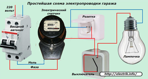
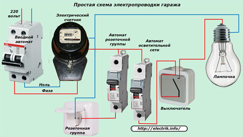
Based on the above recommendations, a 220-volt single-phase wiring diagram in a garage takes on the following structure.
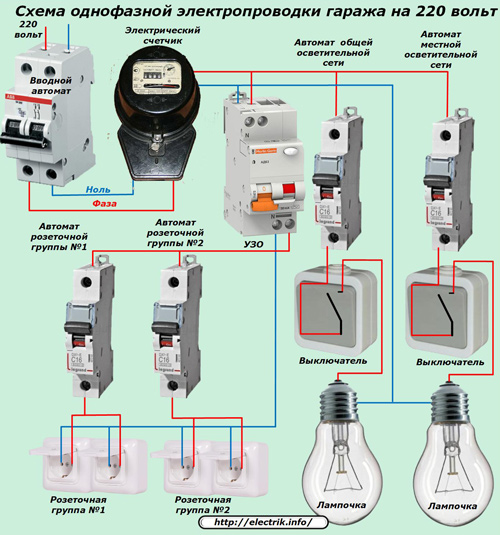
To simplify the picture, it does not show the connection and wiring of the protective PE conductor. For such a power circuit, a three-wire cable must be used.
At three-phase power supply 380 volts The garage wiring diagram is carried out according to the same principles, but it separates consumers according to the number of phases and supply voltage, as shown in the circuit diagram below.
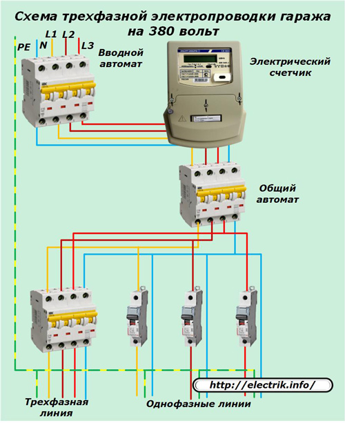
To simplify, it shows only circuit breakers without other protective devices that each garage owner chooses, taking into account the specific conditions of its operation.
Consumers are connected via three-phase network power lines with a five-core cable, and single-phase - with a three-core cable.
When single-phase consumers are working, they try to keep the load uniform in all phases, avoid overloads on any one.
See also: Engineering communications in a garage house on video -
See also at e.imadeself.com
:

