Categories: Practical Electronics, Electrical connection of equipment, Safety precautions
Number of views: 100849
Comments on the article: 17
Isolation transformer in a home electrician workshop
How the isolation transformer works
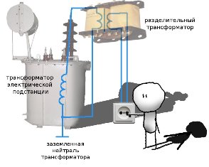
 An isolation transformer is a transformer that is designed for electrical (experts say - galvanic) separation of the power supply network and the consumer of electricity. Consumers are us and why divide us? For safety!
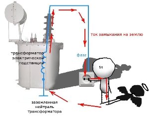
The main task of the isolation transformer is to increase electrical safety due to the fact that its secondary circuits do not have electrical connection with the ground, and therefore with the grounded neutral of the transformer substation - a voltage source.
In this case, the occurrence of an electrical breakdown on the case does not cause overcurrents, and the device itself remains in working condition. If a person accidentally touches a part of a device that is accidentally energized, the leakage current will not exceed a life-threatening threshold and tragedy will not happen.
Isolation transformer - to the home workshop
Thus, isolation transformer far from superfluous element in home workshop, especially if he has to deal with the repair of household appliances. Non-industrial isolation transformers are not on sale, but it is not difficult to make one yourself on the basis of a suitable transformer from domestic televisions of the past generation.
Will fit unified transformer TS almost any power, since modern electrical assistants at home do not differ much voracity. The alteration method is universal and does not require special skills, and therefore, everyone who knows how to handle a soldering iron and measure voltage can afford it.
For an example I will give a ready-made design based on TS-250M.
How to make an isolation transformer
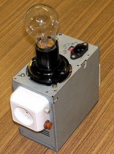
The finished transformer is housed in a case from a computer power supply and is supplemented by some more functions, about which later. A complete TC-250 diagram is shown below.

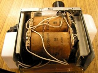
Consider a fragment of the circuit that interests us and which will be modernized. In the standard scheme, two half-windings 1- 2 and 1 '-2' are connected in series and are connected to a 220 volt outlet. (Half-windings are a word meaning that each winding of a transformer is divided into two identical parts, and these half-windings are placed on two identical frames, as in the photo above. On new transformers, the windings are not connected to each other).
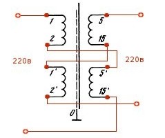
Accordingly, a voltage of 208 volts is removed from the half-windings 5-15 and 5'-15 '(according to the transformer passport) to power the secondary circuits. Actually on the given instance, this voltage was 216 volts at idle. It is easy to guess that each of the primary half-windings is designed for 110 volts, and the secondary ones for 104 volts (108 volts).
The change in the circuit shown below will allow you to get 220 volts at the transformer output. Now, 1-2 and 5'-15 'are used as primary transformer semi-windings, and 1'-2' and 5-15 as secondary semi-windings. Due to the identity of the winding data of the pairs of semi-windings, the input and output voltages will always be equal. Fig. 6
It should be borne in mind that the power transmitted to the load by the transformer is now limited by the power of the winding with a lower permissible current. In the case under consideration, for a winding 5-15 (5'-15 '), the maximum current is 0.8 amperes, which means that the maximum power according to the formula P = I x U is limited and equal to P = 0.8 A x 220 V = 176 W.
In practice, such power will be abundant in most cases. One should also not be afraid of troubles due to the fact that 110 volts are supplied to the semi-winding 5'-15 'instead of the calculated 104-x.Firstly, the transformer will still work in light, underloaded mode (176 watts instead of 250), and secondly, the letter M in the transformer marking indicates that the transformer is resistant to overloads and overvoltages.
We return to the specific design of the isolation transformer.
The photo shows a socket for connecting a load with a fuse and an indicator lamp in the socket. And for what, then, a cartridge with an incandescent lamp on the upper plane, you ask? The answer is a revision that significantly expands the capabilities of the device.
Additional functions of the isolation transformer
The essence of the refinement is clear from the diagram below.

The lamp is connected in series in the primary winding of the transformer, but can be shunted by the switch remaining here from the computer power supply. In this case, we have a conventional isolation transformer. With the switch open, the transformer turns into a scan tool.
With its help, it is now easy to carry out simple operations about troubleshooting devices with switching power supplies. Consider this on the example of a television. To do this, connect it to the outlet of a transformer connected to the network, the switch is open. We turn on the TV with the remote control or the button and fix the lamp behavior:
- nothing happens - a break in the power cord, the input fuse of the TV burned out, the input circuit of the power supply burned out;
- when the TV is turned on, the lamp lights up with a steady full light - a short circuit in the power cord, in the input circuits of the power supply;
- the lamp flashed brightly and went out - the power supply is working, you need to check the main board of the TV.
It should be noted that checking the device (TV, in this case) occurs in a sparing mode and does not lead to further damage to the device under test.
Undervoltage AC for testing high voltage circuits
Have you ever checked a 220 volt electrical circuit? After all, is truth dangerous? With the help of an additional transformer output of ~ 36 volts, this can be done without any risk to health.
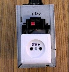
To implement this mode, it is enough to connect the windings 8-8 ', 6-6' and 4-4 'in series and bring the resulting voltage to an external outlet. In the photo it was signed - "36V", and is located on the opposite side from the output, 220-volt outlet side. Now boldly connect your device to it and track the flow of current in the circuits, without fear of touching the live part of the circuit element with your hand.
+ 12 volts for checking and tuning car electronics
Another addition is included in the design - the presence of free windings made it possible to integrate a twelve-volt integral stabilizer into the circuit. With it, you can check and configure various automobile and other devices designed for this voltage.
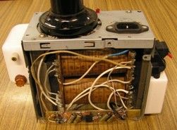
The stabilizer 7812 is turned on as standard and has no features. In the photo below it can be seen below, on the bar of foil fiberglass. The 12 volt output terminals are led above the 36 volt AC outlet, and the +12 volt LED presence indicator is on the top panel of the structure.
For advanced electricians and beginner electronics
The proposed design is extremely simple, but it is able to solve more complex problems. This is a check and repair of devices with switching power supplies, in particular, televisions and switching power supplies of computers.
Checking the operability of the input circuits of switching power supplies using a series-connected incandescent lamp is mentioned above in the article and is described in detail on the Internet pages. I only note that with the help of the design offered to your attention, it is convenient and simple to carry out, without causing difficulties even for a novice repairman.
At the same time, not everyone knows that most switching power supplies are capable of starting from low voltages (no load, of course). Therefore, if you connect the instrument under study to a 36-volt outlet, then with the help of measuring instruments you can verify the serviceability or failure of the start-up unit.
Again, having powered the start-up circuit with a constant voltage of +12 volts from the described device, it is easy to check to check the operation of the generator chip and its strapping, other elements of the circuit. It should be noted that all work is carried out with galvanic isolation from the supply network and with life-safe voltages.
All soldering work, installation of electrical circuits should be carried out with the device disconnected from the mains! This will not only save your health, but also prevent the failure of circuit elements in the event of an accidental circuit.
Nikolay Martov, e.imadeself.com
See also at e.imadeself.com
:

