Categories: Practical Electronics, How does it work
Number of views: 81961
Comments on the article: 5
How is a computer power supply and how to start it without a computer
All modern computers use ATX power supplies. Previously, AT standard power supplies were used, they did not have the ability to remotely start a computer and some circuitry solutions. The introduction of the new standard was associated with the release of new motherboards. Computer technology is rapidly developing and developing, so there was a need to improve and expand motherboards. Since 2001, this standard was introduced.
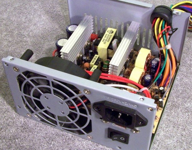
Let's look at how the ATX computer power supply works.
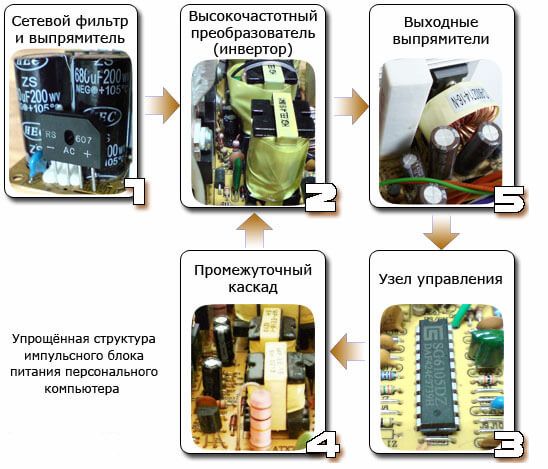
Arrangement of elements on the board
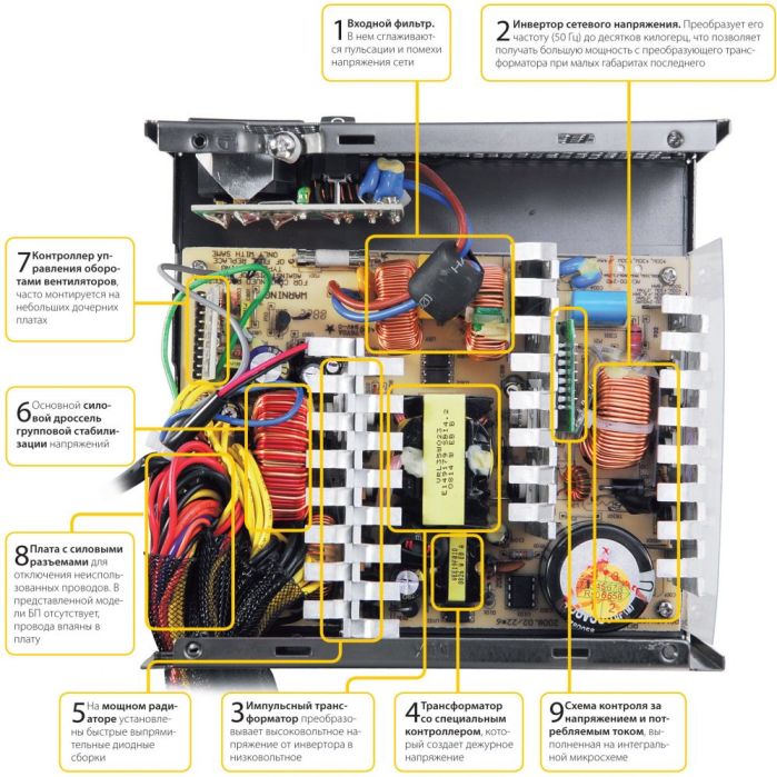
First, take a look at the picture, all the nodes of the power supply are signed on it, then we will briefly consider their purpose.
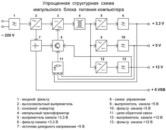
In order for you to understand what will be discussed later, get acquainted with the structural diagram of the power supply side.
But the electrical circuit diagram, broken into blocks.
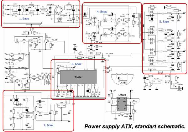
At the input of the power supply is an electromagnetic interference filter from the inductor and capacity (1 unit). In cheap power supplies it may not be. The filter is needed to suppress interference in the power supply network resulting from operation switching power supply.
All switching power supplies can degrade the parameters of the power supply network, unwanted interference and harmonics appear in it, which interfere with the operation of radio transmitting devices and other things. Therefore, the presence of an input filter is highly desirable, but comrades from China do not think so, therefore they save on everything. Below you see a power supply without an input choke.
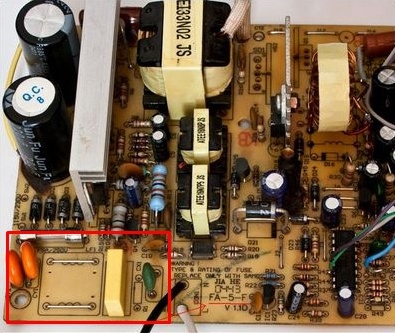
Further, the mains voltage is supplied to rectifier diode bridge, through a fuse and a thermistor (NTC), the latter is needed to charge the filter capacitors. After the diode bridge, another filter is installed, usually a couple of large electrolytic capacitors, be careful, there is a lot of tension on their conclusions. Even if the power supply is disconnected from the mains, you must first discharge them with a resistor or incandescent lamp before touching the board with your hands.
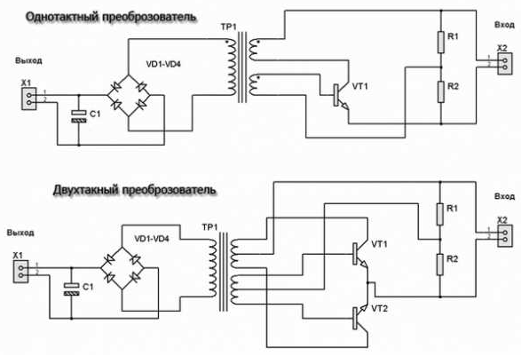
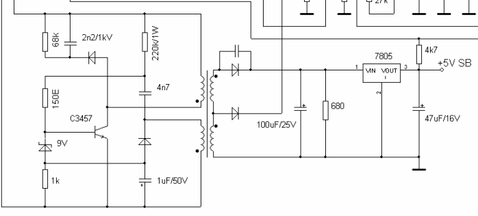
After the smoothing filter, the voltage supplied to the pulse power supply circuit is complicated at first glance, but there is nothing superfluous in it. First of all, the source of standby voltage (2 block) is powered, it can be performed according to a self-generating circuit, or it can be on a PWM controller. Usually - a pulse converter circuit on a single transistor (single-cycle converter), at the output, after the transformer, a linear voltage converter (KENKU) is installed.
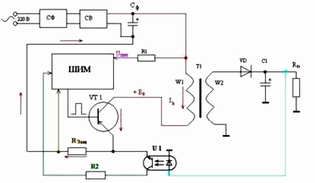
A typical circuit with a PWM controller looks something like this:
Here is an enlarged version of the cascade diagram from the above example. The transistor is in the self-generating circuit, the frequency of operation of which depends on the transformer and the capacitors in its bundle, the output voltage from the zener diode rating (in our case 9V), which plays the role of feedback or a threshold element that shunts the base of the transistor when a certain voltage is reached. It is further stabilized to level 5V, by a linear integral stabilizer of sequential type L7805.
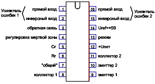
Standby voltage is needed not only to generate the enable signal (PS_ON), but also to power the PWM controller (block 3). ATX pyatnia computer units are most often built on a TL494 chip or its equivalents. This unit is responsible for controlling power transistors (4 block), voltage stabilization (using feedback), protection against short circuit. In general, 494 is iconic microcircuit It is used in pulse technology very often, it can also be found in powerful power supplies for LED strips. Here is her pinout.
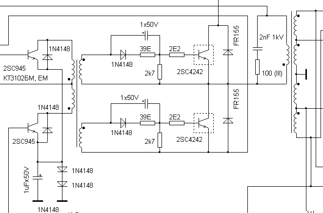
On the given example power transistors (2SC4242) of 4 blocks are switched on through a “swing” performed on two keys (2SC945) and a transformer. The keys can be any, like the other elements of the binding - it depends on the specific scheme and manufacturer. Both key pairs are loaded on the primary windings of the respective transformers. A buildup is needed, since a decent current is needed to control bipolar transistors.
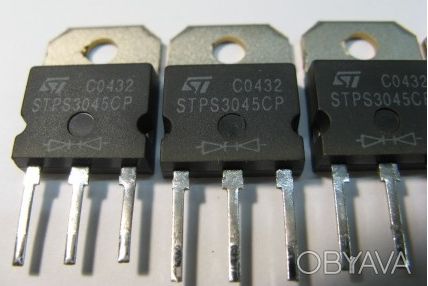
The last cascade is output rectifiers and filters, there are taps from the transformer windings, Schottky diode assemblies, a group filter choke and smoothing capacitors. A computer power supply unit generates a number of voltages for the functioning of the motherboard nodes, power supply for input / output devices, HDD power and optical drives: + 3.3V, + 5V, + 12V, -12V, -5V. A cooling cooler is also powered from the output circuit.
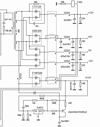
Diode assemblies are a pair of diodes connected at a common point (common cathode or common anode). These are fast diodes with a low voltage drop.
Additional functions
Advanced models of computer power supplies can optionally be equipped with a cooler speed control board, which adjusts them to the appropriate temperature, when you load the power supply, the cooler spins faster. Such models are more comfortable to use, because they create less noise at low loads.
In cheap power supplies, the cooler is connected directly to the 12V line and runs at full power constantly, this increases its wear and tear, as a result of which the noise will become even greater.
If your power supply has a good margin of power, and the motherboard and components are quite modest in consumption, you can solder the cooler to the 5V or 7V line by soldering it between the + 12V and + 5V wires. Plus cooler to the yellow wire, and minus to the red. This will reduce the noise level, but do not do this if the power supply is fully loaded.
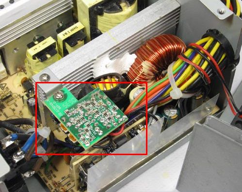
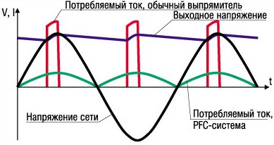
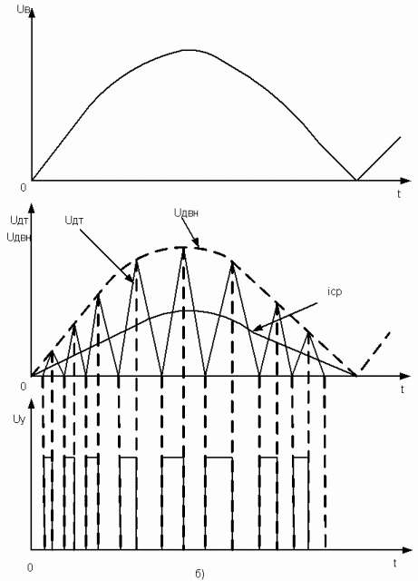
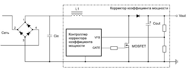
Even more expensive models are equipped with an active power factor corrector, as already mentioned, it is needed to reduce the influence of the power source on the mains. It generates the necessary voltage at the input stages of the IP, while maintaining the original shape of the supply voltage. It’s a rather complicated device and it makes no sense to talk more about it within the framework of this article. A series of diagrams shows the approximate meaning of using the corrector.
Health Check
The IP is connected to the computer through a standardized connector, it is universal in most units, with the exception of specialized power supplies that can use the same terminal block, but with a different pinout, let's look at the standard connector and the purpose of its outputs. He has 20 conclusions, on modern motherboards additional 4 conclusions are connected.
In addition to the main 20-24 pin power connector, wires come out of the unit with pads for connecting voltage to the hard drive, the SATA and MOLEX optical drive, additional processor power, a video card, and power for the floppy drive. You can see all their pinouts in the picture below.
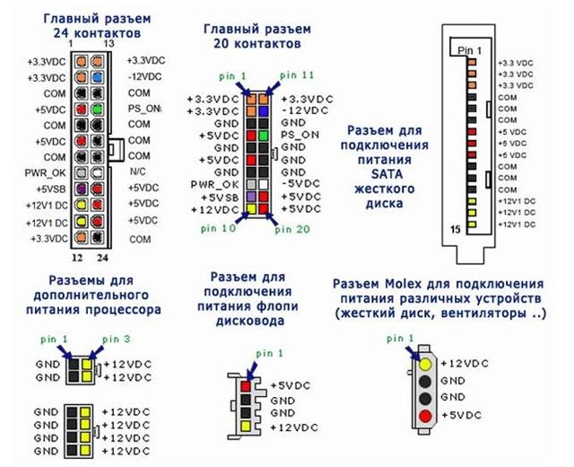

The design of all connectors is such that you do not accidentally insert it upside down, this will lead to equipment failure. The main thing to remember: the red wire is 5V, the yellow is 12V, the orange is 3.3V, the green is PS_ON is 3 ... 5V, the violet is 5V, these are the main ones that must be checked before and after the repair.
In addition to the total power of the power supply, power plays a large role, or rather, the current of each of the lines, usually they are indicated on a sticker on the block body. This information will come in handy if you are planning to run your ATX power supply without a computer to power other devices.

When checking the unit, it is advisable to disconnect it from the motherboard, this will prevent excess voltages above the nominal (if the unit is still not working). But at idle, they do not recommend starting it, this can lead to problems and damage.Yes, and the idle voltage may be normal, but under load significantly sag.
In high-quality power supplies, protection is installed that disconnects the circuit when deviating from normal voltages, such instances will not turn on without load at all. Next, we will consider in detail how to turn on the power supply without a computer and what kind of load can be hung.
Using a power supply without a computer
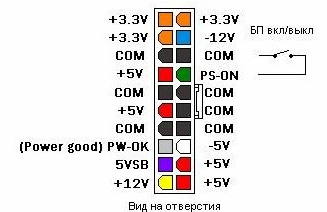
If you insert the plug into the outlet and turn on the toggle switch on the rear panel of the unit, there will be no voltage at the terminals, but there should be a voltage on the green wire (from 3 to 5V), and purple (5V). This means that the standby power supply is normal, and you can try to start the power supply.
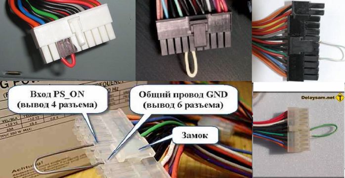
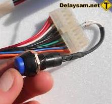
In fact, everything is quite simple, you need to close the green wire to the ground (any of the black wires). It all depends on how you will use the power supply, if for verification, then you can do it with tweezers or a paper clip. If it will be turned on constantly or you will turn off its floor line 220V, then a paper clip inserted between the green and black wires working solution.
Another option is to install a latch button or a toggle switch between the same wires.
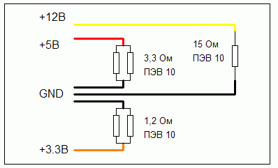
In order for the power supply voltages to be normal when checking it, you need to install a load unit, you can make it from a set of resistors according to this scheme. But pay attention to the value of the resistors, a large current will flow through each of them, on the 3.3 volt line about 5 Amperes, on the 5 volt line - 3 Amperes, on the 12V line - 0.8 Amperes, and this is from 10 to 15W of total power on each line .
Resistors need to be selected appropriate, but they can not always be found on sale, especially in small cities where there is a small selection of radio components. In other versions of the load circuit, the currents are even greater.
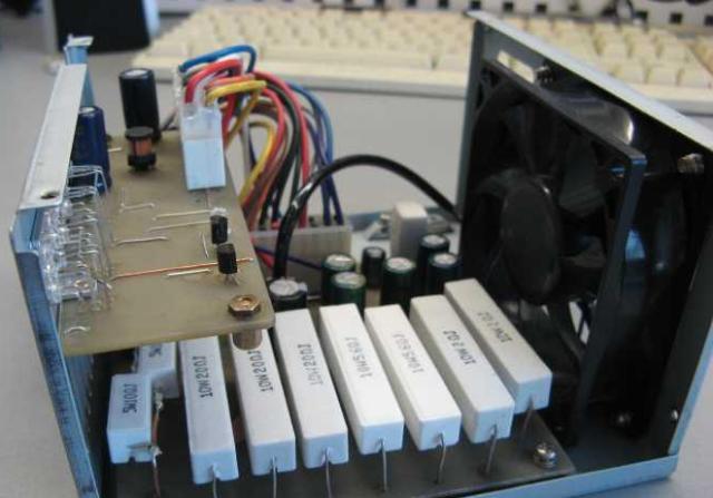
One of the options for performing such a scheme:
Another option is to use incandescent or halogen lamps, they are suitable for 12V from a car, they can also be used on lines with 3.3 and 5V, you just need to choose the right power. Better yet, find a car or motorcycle 6V incandescent lamp and connect several pieces in parallel. 12V high power LED bulbs are currently on sale. For 12V line can use led strip.
If you plan to use a computer power supply, for example, to power an LED strip, it would be better if you slightly load the 5V and 3.3V lines.
Conclusion
ATX power supplies are great for powering amateur radio designs and as a source for a home lab. They are quite powerful (from 250, and modern ones from 350W), while you can find them on the secondary market for a penny, old AT models are also suitable, to run them you just need to short the two wires that used to go to the system unit button, PS_On signal to they are not.
If you are going to repair or restore such a technique, do not forget about the rules for safe work with electricity, that there is mains voltage on the board and capacitors can remain charged for a long time.
Turn on unknown power supplies through the light bulb so as not to damage the wiring and the circuit board tracks. With a basic knowledge of electronics, they can be converted into a powerful charger for car batteries or to the laboratory power supply. For this, the feedback circuits are changed, the source of standby voltage and the starting circuit of the unit are finalized.
See also at e.imadeself.com
:
