Categories: Featured Articles » Practical Electronics
Number of views: 89707
Comments on the article: 3
Home Lab Power Supplies
See the first part of the article here: Power supplies for electronic devices
 In terms of everything that was said above, the most reasonable and least costly seems to be manufacture of transformer power supply. A suitable ready-made transformer for powering semiconductor structures can be selected from old tape recorders, tube televisions, three-program loudspeakers and other obsolete equipment. Ready-made network transformers are sold in radio markets and in online stores. You can always find the right option.
Externally, the transformer is a W-shaped core made of sheets of special transformer steel. On the core is a plastic or cardboard frame on which the windings are located. The plates are usually varnished so that there is no electrical contact between them. In this way they fight eddy currents or Foucault currents. These currents just warm the core, it's just a loss.
For the same purposes, transformer iron is made of large crystals, which are also isolated from each other by oxide films. On transformer iron of very large sizes, these crystals are visible to the naked eye. If such iron is cut with roofing scissors, then the cut resembles a hacksaw blade for metal, contains small cloves.
The transformer in the power supply performs two functions at once. Firstly, this is a decrease in the mains voltage to the desired level. Secondly, it provides galvanic isolation from the mains: the primary and secondary windings are not connected to each other, the electrical resistance is ideally infinite. The connection of the primary and secondary windings is carried out through an alternating magnetic field of the core created by the primary winding.
Simplified transformer design
When buying or self-winding a transformer, you should be guided by the following parameters, which are expressed by only four formulas.
The first of them can be called the law of transformation.
U1 / U2 = n1 / n2 (1),
A simple example. Since this is just a network transformer, the voltage on the primary winding will always be 220V. Suppose that the primary winding contains 220 turns, and the secondary 22 turns. This is a fairly large transformer, so it has few turns per one volt.
If a voltage of 220V is applied to the primary winding, then the secondary winding will produce 22V, which fully corresponds to the transformation coefficient n1 / n2, which in our example is 10. Suppose that a load that consumes exactly 1A of current is included in the secondary winding. Then the primary current will be 0.1A, since the currents are in the inverse ratio.
The power consumed by the windings: for the secondary 22V * 1A = 22W, and for the primary 220V * 0.1A = 22W. This calculation shows that the power of the primary and secondary windings are equal. If there are several secondary windings, then when calculating their power, you should add it, this will be the power of the primary winding.
It follows from the same formula that it is very simple to determine the number of turns per volt: it is enough to wind a test winding, for example, 10 turns, measure the voltage on it, divide the result by 10. The number of turns per volt will help a lot when you need to wind the winding voltage. It should be noted that the windings must be wound with a certain margin, taking into account the "sagging" voltage on the windings themselves and on the regulating elements of the stabilizers. If the minimum voltage requires 12V, then the winding can be rated at 17 ... 18V. The same rule should be observed when buying a finished transformer.
The total power of the transformer is calculated as the sum of the capacities of all secondary windings, as described above. Based on this calculation, you can choose a suitable core, or rather its area. The formula for choosing the core area :.
Here S is the core area in square centimeters, and P is the total load power in watts. For a W-shaped core, the area is the cross section of the central rod on which the windings are located, and for a toroidal cross section, the torus. Based on the calculated core area, you can select the appropriate transformer iron.
The calculated value should be rounded to the nearest larger standard value. All other calculated values in the calculation process are also rounded up. If, suppose, the power is 37.5 watts, then it is rounded up to 40 watts.
After the core area has become known, the number of turns in the primary winding can be calculated. This is the third calculation formula.

Here n1 is the number of turns of the primary winding, U1 - 220V - voltage of the primary winding, S is the core area in square centimeters. An empirical coefficient of 50, which can vary within certain limits, deserves special attention.
If it is required that the transformer does not enter into saturation, does not create unnecessary electromagnetic interference (especially relevant for sound-reproducing equipment), this coefficient can be increased to 60. In this case, the number of turns in the windings will increase, the operation mode of the transformer will be facilitated, the core will no longer be able to enter in saturation. The main thing is that all windings fit.
After the power of the transformer is determined, the turns and currents in the windings are calculated, it's time to determine the cross-section of the wire of the windings. It is assumed that the windings are wound with a copper wire. This calculation will help to fulfill the formula:
Here, di mm, Ii A, respectively, the diameter of the wire and the current of the i-th winding. The calculated wire diameter should also be rounded to the nearest larger standard value.
That's actually the whole simplified calculation of a network transformer, for practical purposes even very sufficient. However, it should be noted that this calculation is valid only for network transformers operating at a frequency of 50 Hz. For transformers made on ferrite cores and operating at a high frequency, the calculation is carried out using completely different formulas, except perhaps the transformation coefficient according to formula 1.
After the transformer is designed, wound or just bought the right size, you can begin to manufacture a power supply, without which no circuit can do.
Unstabilized Power Supplies
The simplest circuitry is unstabilized power supplies. They are used quite often in various designs, which simplifies the circuit without affecting its functionality. For example, powerful audio amplifiers most often they are fed from an unstabilized source, since it is almost impossible to notice by ear that the supply voltage has changed by 2 ... 3 volts. There is also no difference at what voltage the relay will operate: if only it would work, and in the future it will not burn out.
Unstabilized power supplies are simple, the circuit is shown in Figure 1.

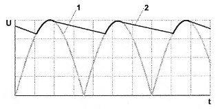
A rectifier bridge with diodes is connected to the secondary winding of the transformer. Although there are a lot of rectifier circuits, a bridge circuit is the most common. At the bridge output, a pulsating voltage with a doubled frequency of the network is obtained, which is typical for all circuits of half-wave rectifiers (Figure 2, curve 1).
Naturally, such a ripple voltage is not suitable for powering transistor circuits: imagine how the amplifier will roar with such power! To smooth the ripple to an acceptable value, filters are installed at the output of the rectifier (Figure 2, curve 2).In the simplest case, it might just be high capacity electrolytic capacitor. The foregoing is illustrated in Figure 2.
Calculation of the capacitance of this capacitor is quite complicated, therefore it is possible to recommend the values tested in practice: for each ampere of current in the load, a capacitor capacity of 1000 ... 2000 μF is required. A lower capacitance value is valid for the case when it is proposed to use a voltage stabilizer after the rectifier bridge.
As the capacitance of the capacitor increases, the ripple (Figure 2, curve 2) will decrease, but will not disappear at all. If ripple is unacceptable, it is necessary to introduce voltage stabilizers into the power supply circuit.
Bipolar power supply
In the case when the source is required to obtain bipolar voltage, the circuit will have to be slightly changed. The bridge will remain the same, but the secondary winding of the transformer should have a midpoint. Smoothing Capacitors there will already be two, each for its own polarity. Such a scheme is shown in Figure 3.

The connection of the secondary windings must be in series - consonant - the beginning of the winding III is connected to the end of the winding II. Dots mark, as a rule, the beginning of the windings. If the industrial transformer and all the outputs are numbered, then you can adhere to this rule: all the odd numbers of the terminals are the beginning of the windings, respectively, even - the ends. That is, with a serial connection, it is necessary to connect the even output of one winding with the odd output of another. Naturally, in no case can you short-circuit the findings of one winding, for example, 1 and 2.
Stabilized power supplies
But quite often, voltage stabilizers are indispensable. The simplest is parametric stabilizerwhich contains only three parts. After the zener diode, an electrolytic capacitor is installed, the purpose of which is to smooth out residual pulsations. Its circuit is shown in Figure 4.

In general, this capacitor is installed even at the output integrated voltage stabilizers type LM78XX. This is required even by the technical specifications (Data Sheet) for microcircuit stabilizers.
A parametric stabilizer can provide up to several milliamps of current in the load, in this case about twenty. In electronic device circuits, such a stabilizer is used quite often. Stabilization coefficient (ratio of input voltage change in %% to output change, also in %%) of such stabilizers, as a rule, no more than 2.
If the parametric stabilizer is supplemented emitter follower, with just one transistor, as shown in Figure 5, the capabilities of the parametric stabilizer will become much higher. The stabilization coefficient of such schemes reaches a value of 70.
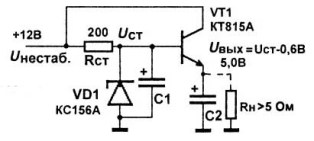
With the parameters indicated in the diagram and the load current 1A, sufficient power will be dissipated on the transistor. Such power is calculated as follows: the collector-emitter voltage difference is multiplied by the load current. In this case, this is the collector current. (12V - 5V) * 1A = 7W. With such power, the transistor will have to be placed on the radiator.
The power given to the load will be only 5V * 1A = 5W. The numbers shown in Figure 5 are quite sufficient to make such a calculation. Thus, the efficiency of a power supply with such a stabilizer with an input voltage of 12V is only about 40%. To slightly increase it, you can reduce the input voltage, but not less than 8 volts, otherwise the stabilizer will stop working.
In order to assemble a voltage stabilizer of negative polarity, it is enough in the considered circuit to replace the n-p-n conductivity transistor with the p-n-p conductivity, change the polarity of the zener diode and the input voltage. But such schemes have already become an anachronism, are not currently used, they were replaced by integrated voltage regulators.
It seemed that it was enough to complete the considered circuit in the integrated version and everything would be in order. But the developers did not begin to repeat the ineffective scheme, its efficiency is too small, and the stabilization is low. To increase the stabilization coefficient, negative feedback has been introduced into modern integral stabilizers.
Such stabilizers were developed on general-purpose op amps, while circuit designer and developer R. Widlar did not propose integrating this op-amp into the stabilizer. The first stabilizer of this kind was the legendary UA723, which required a certain number of additional parts when installing.
A more modern version of integral stabilizers are LM78XX series stabilizers for voltage of positive polarity and LM79XX for negative. In this marking 78, this is actually the name of the microcircuit - stabilizer, the letters LM in front of the numbers may be different, depending on the particular manufacturer. Instead of the letters XX, numbers are inserted indicating the stabilization voltage in volts: 05, 08, 12, 15, etc. In addition to voltage stabilization, microcircuits have protection against short circuit in the load and thermal protection. Just what is required to create a simple and reliable laboratory power supply.
The domestic electronic industry produces such stabilizers under the brand name KR142ENXX. But the markings are always encrypted with us, so the stabilization voltage can only be determined by reference or memorized as poems at school. All of these stabilizers have a fixed output voltage value. A typical wiring diagram for the 78XX series stabilizers is shown in Figure 6.

However, they can also be used to create regulated sources. An example is the diagram shown in Figure 7.

The disadvantage of the circuit can be considered that the regulation is carried out not from zero, but from 5 volts, i.e. from voltage stabilization microcircuit. It is not clear why the stabilizer leads are numbered as 17, 8, 2, when in fact there are only three of them!
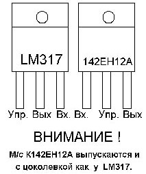
And Figure 9 shows how to assemble an adjustable power supply based on the original bourgeois LM317, which can be used as a laboratory one.

If a bipolar regulated source is required, it is easiest to assemble two identical stabilizers in one housing, feeding them from different transformer windings. At the same time, output the output of each stabilizer to the front panel of the unit with separate terminals. It will be possible to switch voltages simply with wire jumpers.
Boris Aladyshkin
See also at e.imadeself.com
: