Categories: Featured Articles » Electrician at home
Number of views: 56624
Comments on the article: 5
TT earthing system - device and features of use
 Electricity comes to our homes and apartments via electric wires of overhead or cable lines from transformer substations. The configuration of these networks has a significant impact on the operational characteristics of the system and, especially, the safety of people and household appliances.
In electrical installations, there is always the technical possibility of equipment damage, emergency conditions, and electrical injuries by humans. Proper organization of the grounding system reduces the risk of risk, maintain health, and eliminate damage to home appliances.
Reasons for using CT grounding system
By its purpose, this scheme is designed for such a case when other common systems cannot provide a high degree of security TN-S, TN-C-S, TN-C. This is very clearly indicated by the clause PUE 1.7.57.
Most often this is due to the low level of technical condition of power lines, especially using bare wires located in the open air and mounted on poles. They are usually mounted in a four-wire circuit:
-
three phases of voltage supply, offset by an angle of 120 degrees between each other;
-
one common zero, performing the combined functions of the PEN conductor (working and protective zero).
They come to consumers from a step-down transformer substation, as shown in the photo below.
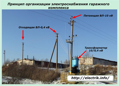
In rural areas, such highways can be very long. It is no secret that wires sometimes break up or break off due to poor quality of twisting, falling branches or whole trees, drafts, gusts of wind, the formation of frost in the cold after wet snow, and for many other reasons.
Wherein zero break occurs quite often, since it is mounted on the bottom wire. And this causes a lot of trouble to all connected consumers due to the occurrence of voltage distortions. In such a circuit, there is no protective PE conductor connected to the grounding circuit of the transformer substation.
Cable lines are much less likely to break off because they are located in closed ground and are better protected from damage. Therefore, they immediately implement the most secure TN-S grounding system, and gradually reconstruct TN-C to TN-C-S. Consumers connected by overhead wires are practically deprived of such an opportunity.
Now many landowners are starting the construction of cottages, entrepreneurs organize trade in separate pavilions and kiosks, manufacturing enterprises create prefabricated living rooms and workshops or even use separate wagons that are temporarily powered by electricity.
Most often, such structures are made of metal sheets that are well-conducting electric current or have moist walls with high humidity. Human safety when in such conditions can provide only the grounding system, made according to the CT scheme. It is specially designed to work in such conditions when the network potential has a high probability of an emergency occurrence on live walls or equipment housings.
Principles of constructing a grounding circuit for a TT system
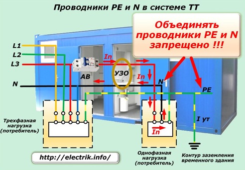
The main safety requirement in this situation is ensured by the fact that the protective PE conductor is created and grounded not at the transformer substation, but at the object of electrical energy consumption without communication with a working N-conductor connected to the ground of the supply transformer.These zeros should not be contacted or combined even when a separate ground loop is mounted nearby.
In this way, all dangerous conductive surfaces of buildings from metal and the body of connected electrical appliances are completely separated from the existing power supply system by the protective PE conductor.
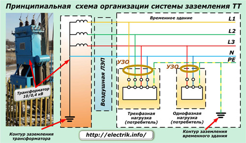
Inside the building or structure, a protective PE conductor is mounted from a rod or strip of metal, which serves as a bus for connecting all hazardous elements with conductive properties. On the opposite side, this protective zero is connected to a separate ground loop. The PE conductor assembled by this method combines all sections that have a risk of hazardous voltage into a single potential equalization system.
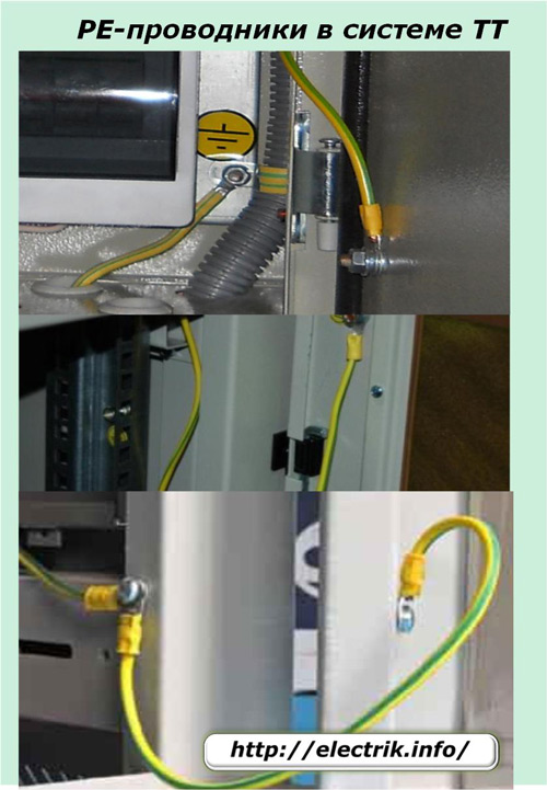
The connection of hazardous metal structures to protective zero can be carried out by a multi-strand flexible wire of increased cross section marked with yellow-green stripes.
At the same time, we will once again draw attention to the fact that it is strictly forbidden to combine structural elements of buildings and metal cases of electrical devices with a working zero N.
Safety requirements in the TT system
Due to an accidental violation of the insulation of the electrical wiring, the voltage potential can suddenly appear in any place of the not connected, but conductive part of the building. A person who touches it and the earth is immediately exposed to an electric current.
Circuit breakers that protect against overcurrents and overloads can only be used indirectly to relieve voltage in this case, since part of the current goes bypassing the working zero chain, and the resistance of the main ground loop must be very low.
In order to secure a person with the operation of circuit breakers, it is necessary to create a condition for the formation of a leakage potential on an open current-carrying part of not more than 50 volts relative to the earth potential. In practice, this is difficult to accomplish for a number of reasons:
-
high multiplicity of short-circuit currents of the time-current characteristic used by the designs of various switches;
-
high ground loop resistance;
-
the complexity of technical algorithms for the operation of such devices.
Therefore, the preference in creating a protective shutdown is given to devices that respond directly to the appearance of a leakage current, branching off from the main calculated path of the load flowing through the PE conductor and localizing it by relieving the voltage from the controlled circuit, which is done only by RCDs or differential machines.
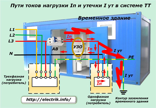
The risks of electrical injuries with this grounding method can be eliminated only if the four main tasks are integrated:
1. proper installation and operation of protective devices such as RCDs or differential machines;
2. maintaining a working zero N in technically sound condition;
3. the use of surge protective devices in the network;
4. proper operation of the local ground loop.
RCD or difavtomaty
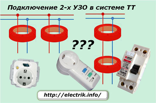
Almost all parts of the building's electrical wiring should be covered by the protection zone of these devices from leakage currents. Moreover, their setpoint for operation should not exceed 30 milliamps. This will ensure that the voltage is disconnected from the emergency section during breakdown of the insulation of the wiring, excludes accidental contact of a person with spontaneously arising dangerous potential, and protects against electrical injury.
Installing a fire protection RCD with an input of 100 ÷ 300 mA at the entrance panel into the house increases the level of safety and ensures the introduction of a second degree of selectivity.
Work Zero N
To RCD circuit correctly determined leakage currents, it is necessary to create technical conditions for it and eliminate errors. And they arise immediately when the chains of the working and protective zeros are combined.Therefore, the working zero must be surely reliably separated from the protective one, and they cannot be connected. (Third reminder!).
Network surge protection
The occurrence of electrical discharges in the atmosphere, associated with the formation of lightning, are random, spontaneous. They can be manifested not only by electric shock to the building, but also by getting into the wires of an overhead power line, which happens quite often.
Power engineers apply protective measures against such natural phenomena, but they do not always turn out to be quite effective. Most of the energy of the struck lightning is diverted from the power transmission line, but some of its share has a harmful effect on all connected consumers.
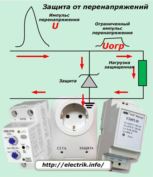
You can protect yourself from the effects of such surges of overvoltages coming along the supply line, using special devices - surge arresters or pulse surge protection devices (SPD).
Maintaining the local ground loop
This task is assigned primarily to the owner of the building. No one else will deal with this issue on their own.
The ground loop is buried mostly in the ground and in this way is hidden from accidental mechanical damage. However, in the soil there are constantly solutions of various acids, alkalis, salts, which cause redox chemical reactions with metal parts of the circuit, forming a layer of corrosion.
Due to this, the conductivity of the metal in the places of contact with the soil deteriorates and the total electrical resistance of the circuit increases. By its magnitude, the technical capabilities of grounding and its ability to conduct fault currents to the earth potential are judged. This is done by conducting electrical measurements.
A working ground loop must reliably pass to the earth potential the setpoint of the residual current device, for example, at 10 milliamps and not distort it. Only in this case, the RCD will work correctly, and the TT system will fulfill its purpose.
If the resistance of the ground loop is higher than normal, then it will prevent the passage of current, reduce it, which can completely eliminate the protective function.
Since the current of operation of the RCD depends on the complex resistance of the circuit and the state of the ground loop, there are recommended values of the resistances that allow for guaranteed operation of the protections. These values are shown in the picture.
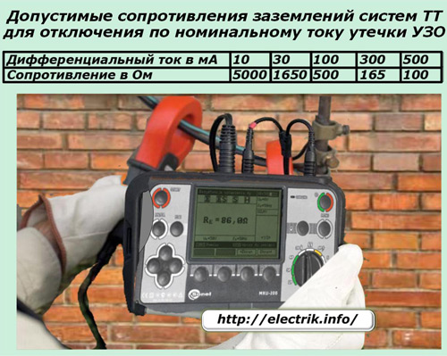
The measurement of these parameters requires professional knowledge and accurate specialized instruments working by megaohmmeter principle, but using a complicated algorithm with an additional connection scheme and a strict sequence of calculations. A high-quality ground loop resistance meter stores the results of its work in memory and displays on the information board.
Using them, using computer technology, graphs of the distribution of the electrical characteristics of the circuit are built and its state is analyzed.
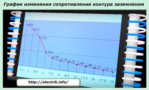
Therefore, such work is carried out by accredited electrical laboratories with special equipment.
Measurement of the insulation resistance of the ground loop must be done immediately after putting the electrical installation into operation and periodically during operation. When the obtained value goes beyond the norm, exceeding it, then create additional sections of the circuit, connected in parallel. The completion of the work performed is checked by repeated measurements.
Dangerous circuit faults in the TT system
When considering the technical requirements for ensuring safety, four main conditions were identified, the solution of which should be implemented in an integrated manner. Violation of any item can lead to sad consequences during the breakdown of the insulation resistance of the phase conductor.
For example, a phase falling on the body of an electrical appliance in case of a faulty RCD or a broken ground loop will result in electrical injury. The circuit breakers installed in the circuit may simply not work, since the current through them will be less than the setting.
Partially correct the situation in this case is possible due to:
-
introduction of a potential equalization system;
-
connecting the second selective protection stage of the RCD to the entire building, which was already mentioned in the recommendations.
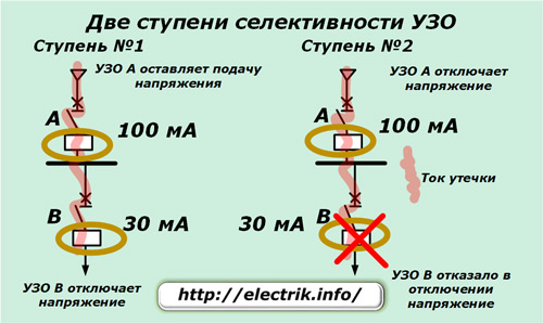
Since the whole organization of work on creating the grounding of the TT system is complex and requires the exact fulfillment of technical conditions, the implementation of such an installation should be trusted only to trained workers.
See also at e.imadeself.com
:
