Categories: Featured Articles » Electrician Secrets
Number of views: 259792
Comments on the article: 13
How to choose a wire cross section for 12 volt lighting networks
 In conversations with customers when discussing 12-volt halogen lighting, for some reason the word "low current" often flickers, which characterizes the corresponding attitude to the choice of wires - which is at hand, then we use it, the voltage is safe.
The voltage of 12 volts is really safe, in the sense that touching a bare wire with such voltage is simply not felt, but the currents in such circuits flow quite large (see. highlights of using safe voltage in everyday life).
Consider food as an example ordinary halogen lamp with a power of 50 W, the current in the primary circuit of the transformer I = 50W / 220V = 0.23A (or, more precisely, a little more, taking into account the efficiency of the transformer), while the current I = 50W / 12V = 4.2 A flows in the secondary circuit of 12 V, which is already 18 times more. If you do not take this fact into account, you may encounter very unpleasant surprises.
One day a man came to me for a consultation and told what he had done in his house halogen lighting, used a reliable induction transformer 1000W at a load of 900W, spent from mounting box a separate wire to each lamp, but at the moment of switching on the wires simply caught fire, and those wires that led from the transformer output to the mounting box.
To the question about the section of the laid wires - the answer: "An ordinary section, as everywhere else - 1.5 mm2". In stationary mode, I = 900W / 12V = 75A should flow through this wire, and even more when switched on. The cross-section of the copper wire under such conditions should be at least 16 mm2. Hence the conclusion: It is important not to forget about the increased currents in the 12 volt circuits and, accordingly, choose the wires. This, however, is sometimes completely insufficient.
Very often we have to deal with complaints that when using transformers of high power (in this case, 200W is already high power), supplying several lamps, the brightness of the lamps decreases markedly with increasing distance from the transformer. Attempts to deal with this problem by increasing the power of the transformer, of course, do not lead to an improvement in the situation, especially since the increase in the power of the lamps used does not help. The fact is that the cause of this phenomenon is commonplace voltage drop on wires in accordance with Ohm's law.
We illustrate what was said on a concrete example:
Suppose you need to power a group of three lamps of 50W each, located at a distance L from the transformer, as shown in the figure:

The equivalent circuit has the form:

Resistance of each lamp Rl = U2/ P = 2.88 Ohm, and the resistance of the wire with a length L and a cross section S

Where ρ - resistivity, in this case copper (0.0173 Ohm mm2/ M).
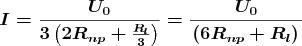
If voltage U is supported at the transformer output0 = 12 V, then the current through each lamp
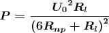
and the power released in the lamp
Using these formulas, easy to calculate power versus wire length. The calculation results are shown in the table (if you click on the picture, the table will load in a larger format):

As can be seen from the table, power drops pretty quickly with increasing wire lengths, This is even more clearly seen in the graphs:

Fig. 3. Loss of lamp power depending on the length of the supply wires
It is possible to avoid noticeable unevenness in the luminous flux of lamps not only through the use of a large cross-section wire, but also by dividing the lamps into groups fed by individual wires, in the limit feeding each lamp with its own wire. In any case, when purchasing lighting equipment, it is useful to ask the seller to give accurate recommendations on the choice of wire cross-section and installation diagram.
Specific recommendations for choosing the wire cross section in the 12 V lighting circuit when using electronic and induction transformers can be found in the corresponding tables.
Tables for selecting the cross-section of wires in low-voltage lighting circuits
As shown earlier, from the analysis of power losses in 12 V lighting networks, the cross-section of wires for halogen lighting of 12 volts should be selected taking into account the total power of the lamps connected to the transformer and the length of these wires.
The approach to determining the cross section of the wires depends on which source is used to power the circuit: electronic or induction. The permissible length of wires in the secondary circuit of electronic power supplies, as a rule, cannot exceed 2 meters (in very rare cases, lengths of up to 3 meters are allowed for high-power transformers). In this case use a wire with the cross section specified in the transformer documentation. If such data are not available, you can tentatively use the data from the table:
Cross-sectional table of copper wires in a 12 V lighting circuit up to 2 meters long (for electronic power supplies). If you click on the picture, the table will load in a larger format.

When using induction transformers, the length of the wire in the secondary circuit is limited only by the voltage drop across the wires and, therefore, can be significantly larger than electronic (pulse) power supplies, subject to compensation by increasing the cross section of the wire.
Below is given table for choosing the cross-section of wires depending on the total power of the lamps connected to the secondary winding of the induction transformer and the length of these wires. It should be borne in mind that the lamps can be divided into groups, each connected with its own wire, in this case, the cross section of the group wire is determined by the table for each group separately. In the limit, it is possible to connect each lamp with its own wire.
Cross-sectional table of copper wires in the 12 V lighting circuit (for induction transformers).

See also at e.imadeself.com
: