Categories: Featured Articles » Electrician Secrets
Number of views: 390289
Comments on the article: 29
How to choose a cable section - designer tips
The article considers the main criteria for choosing a cable section, gives examples of calculations.
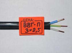 In markets, you can often see hand-written signs indicating which cable must be purchased by the buyer depending on the expected load current. Do not believe these signs, as they mislead you. The cable cross-section is selected not only by operating current, but also by several parameters.
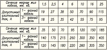
First of all, it must be borne in mind that when using a cable at the limit of its capabilities, the cable cores heat up several tens of degrees. The current values shown in Figure 1 suggest heating of the cable cores to 65 degrees at an ambient temperature of 25 degrees. If several cables are laid in one pipe or tray, then due to their mutual heating (each cable heats all other cables), the maximum allowable current is reduced by 10 - 30 percent.
Also, the maximum possible current decreases at elevated ambient temperatures. Therefore, in a group network (a network from shields to fixtures, plug sockets and other electrical receivers), cables are usually used at currents not exceeding 0.6 - 0.7 from the values shown in Figure 1.
Fig. 1. Permissible continuous current of cables with copper conductors
On this basis, the widespread use of circuit breakers with a rated current of 25A to protect the outlet networks laid with cables with copper conductors with a cross section of 2.5 mm2 is a danger. Tables of reducing coefficients depending on the temperature and the number of cables in one tray can be found in the Electrical Installation Rules (PUE).
Additional restrictions arise when the cable is long. At the same time, voltage losses in the cable can reach unacceptable values. As a rule, when calculating the cables, the maximum losses in the line are no more than 5%. Losses are not difficult to calculate if you know the resistance value of the cable cores and the estimated load current. But usually for calculation of losses tables of dependence of losses on the moment of loading are used. The load moment is calculated as the product of the cable length in meters and power in kilowatts.
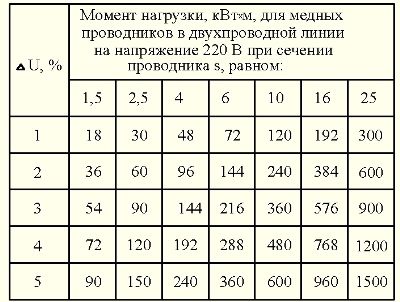
The data for calculating losses at a single-phase voltage of 220 V are shown in table1. For example, for a cable with copper conductors with a cross-section of 2.5 mm2 with a cable length of 30 meters and a load power of 3 kW, the load moment is 30x3 = 90, and the loss will be 3%. If the calculated loss value exceeds 5%, then it is necessary to choose a cable with a larger cross section.
Table 1. The load moment, kW x m, for copper conductors in a two-wire line at a voltage of 220 V for a given section of the conductor
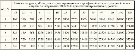
According to table 2, you can determine the loss in a three-phase line. Comparing tables 1 and 2, it can be noted that in a three-phase line with copper conductors with a cross section of 2.5 mm2, a loss of 3% corresponds to a six times greater load moment.
A triple increase in the load moment occurs due to the distribution of the load power in three phases, and a double increase due to the fact that the current in the neutral conductor is zero in a three-phase network with a symmetrical load (identical currents in phase conductors). With an unbalanced load, losses in the cable increase, which must be taken into account when choosing the cable section.
Table 2. The load moment, kW x m, for copper conductors in a three-phase four-wire line with zero voltage of 380/220 V for a given section of the conductor (to enlarge the table, click on the figure)
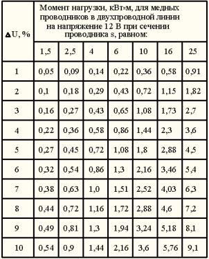
Losses in the cable are strongly affected when using low-voltage, for example, halogen lamps. This is understandable: if 3 Volts drops on the phase and neutral conductors, then at a voltage of 220 V we most likely will not notice this, and at a voltage of 12 V the voltage on the lamp will drop by half to 6 V.That is why transformers for powering halogen lamps must be brought as close as possible to the lamps. For example, with a cable length of 4.5 meters with a cross section of 2.5 mm2 and a load of 0.1 kW (two lamps of 50 W each), the load moment is 0.45, which corresponds to a loss of 5% (Table 3).
Table 3. The load moment, kW x m, for copper conductors in a two-wire line at a voltage of 12 V for a given section of the conductor
The above tables do not take into account the increase in the resistance of conductors from heating due to the flow of current through them. Therefore, if the cable is used at currents of 0.5 or more of the maximum allowable cable current of a given section, then an amendment must be made. In the simplest case, if you expect to receive losses of no more than 5%, then calculate the cross section based on the losses of 4%. Also, losses can increase with a large number of cable conductor connections.
Cables with aluminum conductors have a resistance of 1.7 times greater compared to cables with copper conductors, respectively, and losses in them are 1.7 times greater.
The second limiting factor for large cable lengths is the excess of the permissible value of the phase-zero circuit resistance. To protect cables from overloads and short circuits, as a rule, use circuit breakers with a combined release. Such switches have thermal and electromagnetic releases.
The electromagnetic release provides instantaneous (tenths and even hundredths of a second) shutdown of the emergency section of the network during a short circuit. For example, a circuit breaker labeled C25 has a thermal release of 25 A and an electromagnetic release of 250A. Circuit breakers of group "C" have a multiplicity of breaking current of the electromagnetic release to thermal from 5 to 10. But at calculation of the line for short circuit current the maximum value is taken.
The general resistance of the phase-zero circuit includes: the resistance of the step-down transformer of the transformer substation, the resistance of the cable from the substation to the input distribution device (ASU) of the building, the resistance of the cable laid from the ASU to the switchgear (RU) and the cable resistance of the group line itself, the cross section of which is necessary to determine.
If the line has a large number of cable conductor connections, for example, a group line of a large number of fixtures connected by a loop, then the resistance of contact connections must also be taken into account. For very accurate calculations, the arc resistance at the fault location is taken into account.
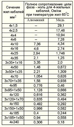
The impedance of the phase-zero circuit for four-wire cables is shown in Table 4. The table takes into account the resistances of both phase and neutral conductors. Resistance values are given at a cable core temperature of 65 degrees. The table is also valid for two-wire lines.
Table 4. The total resistance of the phase-zero circuit for 4-core cables, Ohm / km at a core temperature of 65aboutFROM
In urban transformer substations, as a rule, transformers with a capacity of 630 kV are installed. And more, having an output impedance Rtp of less than 0.1 Ohm. In rural areas, transformers of 160 - 250 kV can be used. And having an output resistance of the order of 0.15 Ohms, and even transformers at 40 - 100 kV. And having an output impedance of 0.65 - 0.25 Ohms.
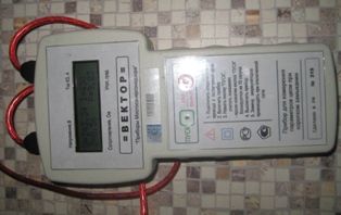
Power supply cables from urban transformer substations to the ASG of houses are usually used with aluminum conductors with a cross-section of phase conductors of at least 70 - 120 mm2. When the length of these lines is less than 200 meters, the resistance of the phase-zero circuit of the supply cable (Rpc) can be taken equal to 0.3 Ohm. For a more accurate calculation, you need to know the length and cross section of the cable, or measure this resistance. One of the instruments for such measurements (the Vector instrument) is shown in Fig. 2.
Fig. 2. The device for measuring the resistance of the phase-zero circuit "Vector"
The resistance of the line must be such that with a short circuit the current in the circuit is guaranteed to exceed the operating current of the electromagnetic release.Accordingly, for the circuit breaker C25, the short circuit current in the line should exceed 1.15 × 10 × 25 = 287 A, here 1.15 is the safety factor. Therefore, the phase-zero circuit resistance for the C25 circuit breaker should be no more than 220V / 287A = 0.76 Ohm. Accordingly, for a circuit breaker C16, the circuit resistance should not exceed 220V / 1.15x160A = 1.19 Ohms and for a circuit breaker C10 - no more than 220V / 1.15x100 = 1.91 Ohms.
Thus, for an urban apartment building, taking Rtp = 0.1 Ohm; Rpc = 0.3 Ohm when using a cable with copper conductors with a cross section of 2.5 mm2 protected by a C16 circuit breaker in the outlet network, the cable resistance Rgr (phase and neutral conductors) should not exceed Rgr = 1.19 Ohm - Rtp - Rpk = 1.19 - 0.1 - 0.3 = 0.79 Ohms. According to table 4 we find its length - 0.79 / 17.46 = 0.045 km, or 45 meters. For most apartments this length is enough.
When using a C25 circuit breaker to protect a cable with a cross section of 2.5 mm2, the circuit resistance should be less than 0.76 - 0.4 = 0.36 Ohm, which corresponds to a maximum cable length of 0.36 / 17.46 = 0.02 km, or 20 meters.
When using a C10 circuit breaker to protect a group lighting line made with a cable with 1.5 mm2 copper conductors, we get the maximum allowable cable resistance of 1.91 - 0.4 = 1.51 Ohms, which corresponds to a maximum cable length of 1.51 / 29, 1 = 0.052 km, or 52 meters. If you protect such a line with a C16 circuit breaker, then the maximum line length will be 0.79 / 29.1 = 0.027 km, or 27 meters.
See also:Why do phase-zero loop resistance measurements be performed by professionals and not hackers
Victor Ch
See also at e.imadeself.com
:

