Categories: Featured Articles » Practical Electronics
Number of views: 57305
Comments on the article: 7
Transistor Test Probe
 In case of repair of electronic devices “Ring” the transistorinstalled in the circuit does not always succeed, so you have to unsolder it from the circuit. Often this interference leads to damage to the printed circuit boards, and sometimes to the transistors themselves. Therefore, it is very good if there is a device at hand that allows you to determine the health of the transistor without evaporating it from the board. Schemes of such devices are given in this article.
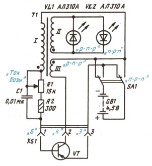
The probe circuit is simple and shown in Figure 1.
The basis of the circuit is a classic blocking generator. The output of such a generator produces short rectangular pulses. Naturally, to get a working blocking generator to the probe connector XS1, you need to get the tested transistor VT. The oscillations are obtained due to the positive feedback in the transformer T1 through the coupling winding I. The optimal feedback value is selected by rotating the variable resistor R1. If the handle R1 is equipped with a scale, then the angle of rotation of the engine can approximately judge the amplifying properties of the transistor.
The probe is powered by three AAA cells or a square battery. Using switch SA1, you can change the polarity of the power on, which allows you to check the transistors of various structures, as shown in the figure.

Figure 1. Transistor probe test circuit
The occurrence of generation is indicated by the LEDs VL1 VL2. When the polarity of the supply voltage changes, the polarity of the output pulses naturally changes, so you have to install two LEDs.
The transformer of the blocking generator is made independently on the Ш6 * 8 core, although, without changing the number of turns, the size of the iron can be slightly increased. Such transformers were used in receivers "Mountaineer" and the like. All windings are made with PEV1-0,2 winding wire. The feedback winding I contains 200 turns, the output winding II 30 turns, the collector winding III 100 turns of the same wire.
The plates of the transformer are assembled end-to-end, as in a DC reactor: W-shaped plates are inserted into the hole of the frame, and jumpers through a thin paper strip on top of the W-shaped plates. When connecting the windings, attention should be paid to their polarity, indicated by points in the diagram: if the generator does not start when a known-good transistor is connected, the ends of one of the windings should be interchanged - collector or base.
A similar circuit was part of a device for testing industrial transistors PPT-5. It’s just that this part was borrowed by radio amateurs, as it proved itself on the good side.
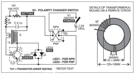
Almost the same scheme was published in one bourgeois publication. It differs little from that described above, and is shown in Figure 2.

Figure 2Another transistor probe circuit
The probe is powered by a single 1.5V cell of type AA or AAA. Switch S2 changes the power supply polarity to test transistors of different conductivity, as indicated in the diagram.
The design of the transformer S is immediately shown in Figure 2. It is made on a ferrite ring of size K10 * 6 * 4 with magnetic permeability NM2000. The collector winding S contains 6 turns, and the base winding P is only 2 turns made by wire PEV2-0.2 mm. However, the diameter of the wire does not matter much, therefore, to increase the mechanical strength, it can be slightly increased. The ring can also be taken with a slightly larger diameter.
The VR resistor sets the probe's operating mode, exactly the same as in the previous circuit. The connection diagram of the LEDs is somewhat simplified, there is no additional winding.The LEDs are ignited by reverse voltage spikes on the collector of the transistor under test at the time of its shutdown.
There are many different schemes for testing transistors, but these two are perhaps the most successful. Their only drawback is the need for winding a transformer.
Boris Aladyshkin
See also at e.imadeself.com
:
