Categories: Featured Articles » Practical Electronics
Number of views: 298,311
Comments on the article: 16
Simple converter 12V to 220V 50Hz
 The article describes a converter circuit made on a modern element base, containing a minimum number of parts and allowing to obtain significant power in the load.
For many years now, on the pages of radio engineering publications, schemes have been published that allow car battery get an alternating voltage of 220V to power various equipment in the "field" conditions. Of course, you can always buy a voltage converter 12 220, but it’s much more interesting to do a voltage converter with your own hands.
The circuitry of such converters is quite simple: the master oscillator controls the operation of powerful output transistors that “swing” the output transformer. The generator, as a rule, was run on microcircuits of a small degree of integration K155, K561 and the like, and contained from two to four cases.
To coordinate powerful output transistors with these microcircuits, it was necessary to introduce additional stages on transistors of small and medium power. The output transistors, which were most often used KT819GM, had to put on a fairly large radiator.
The modern elemental base allows us to significantly simplify such schemes. The proposed scheme, in comparison with the just described, contains a minimum number of parts.
A specialized chip KR1211EU1 is used as a master oscillator. By the way, the domestic microcircuit does not have foreign analogues.
As the output keys, powerful IRL2505 field effect transistors are used, which are often used in various automotive devices.
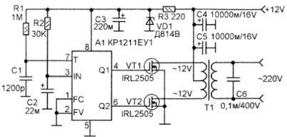
KR1211EU1 has two outputs - direct and inverse. These are conclusions 4 and 6 respectively. The signal level at these outputs is sufficient for direct control output transistors: Transistors open with high-level pulses. Moreover, between them the microcircuit itself forms a pause (low level), which for a certain period of time, sometimes called “dead time”, keeps both transistors closed. This is done in order to exclude the appearance of through current when opening both keys at once.
Electrical schematic diagram of a 12V to 220V 50Hz converter
The required frequency of the generator is set by the chain R1 - C1, the circuit R2 - C2 is used as a starting.
Pin 1 of the microcircuit allows you to disable pulse generation, for which a high level should be applied to it. This property can be used for remote control or for protection. In this circuit, these functions are not used, so pin 1 is simply connected to a common wire.
The output push-pull stage is made on a transformer T1 and key transistors VT1, VT2, which are used as IRL2505. The open channel resistance of these transistors is 0.008 ohms. This is commensurate with mechanical contact resistance, therefore, the power dissipated by the transistor in the open state is small, even at high currents, which allows in some cases to abandon the use of radiators.
Direct current IRL2505 up to 104A, pulse 360A. Such parameters make it possible to use an output transformer with a power of up to 1000W, at which it is possible to remove up to 400W at a voltage of 220V.
The advantage of this converter is that you can use any ready-made transformer that has two output windings for 12V. The power of the transformer depends on the load and should be 2.5 times higher: suppose that the load power is 30W. Then the power of the transformer must be at least 30 * 2.5 = 75W.
With an output power of not more than 200 W, transistors can not be installed on radiators.
About the details. Microcircuit A1 receives power from the parametric stabilizer R3, VD1, C3.As a zener diode VD1, anyone with a stabilization voltage of 8 ... 10V is suitable.
Electrolytic capacitors imported. If there are no capacitors at 10000 mkf, (C4, C5) they can be replaced with 4700 mkf capacitors, turning them on in parallel.
Capacitor C6 serves to suppress the output of high-frequency pulses. It can be of the type K-73-17 or a similar import.
During installation, one should not forget that already at a power of 400 W, the current consumed from the battery through the 12V circuit can reach 40A, so the wires for connecting to the battery should be of sufficient cross section and the shortest possible length.
Boris Aladyshkin
Practical Electrical Engineering and Electronics
See also at e.imadeself.com
:

