Categories: Featured Articles » Sharing experience
Number of views: 116739
Comments on the article: 23
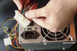
DIY computer power supply repair
General recommendations for the repair of computer power supplies for stationary computers.
 Low reliability RRussian electric networks is the cause of the failure of household equipment. In the system units of stationary computers, after the completion of the operating system, despite the apparent inaction, Power Supply remains permanently connected to the network. In this state, he is at risk of exposure to power surges.
The use of network filters is corrected only by the fact that they have a shutdown button, which is more effective protection than the specified protective and filtering functions.
Most system power supplies are assembled from ordinary, so-called non-name (no name) manufacturers. In this case, repairing the power supply does not justify the means.
But if you have installed a high-quality power supply of famous manufacturers and power exceeding 400 watts, then it is more reasonable to buy a new one may be an attempt to self-repair a failed power supply.
The first thing to remember is that life-threatening voltage of 220 volts is used in the power supply. The power supply circuit contains elements such as high-capacity capacitors that can store voltage for a long time. If you never held in your hands soldering iron, then it would be wiser for you to ask someone from your comrades, or think about buying a new one.
So, proceed to repair the computer power supply. You will hardly find such a concept on the Internet. There are several typical power supply circuits, so you have to navigate along the way.
Remove the cover of the power supply. Large radiators will be located on the board, necessary to remove heat from the power elements. Most of the malfunctions are the failure of these particular power elements located in the primary circuit.
For reliability, you should unsolder these elements (often you have to unsolder by braiding - take a braid, for example a shielding braid from a high-frequency cable, lean against a leg that needs to be soldered, a powerful soldering iron rests, dipped in rosin for a second. Solder from the board will tin off small braid hairs and gradually completely leave the board.
Attaching patience and accuracy, this method allows you to free a group of elements located, for example, on one radiator). Transistor test consists in dialing (checking for conductivity) transitions. Usually, not knowing the pinouts of the element, they begin to ring all the legs together. In a working transistor of a simple type, one leg should ring with the other two, while in the reverse polarity there should be no conductivity. It is the same between the other two - there should also not be calls. See more about this here: How to check the transistor.
To ensure the integrity of the elements, it is recommended to find their data (datasheet) on the Internet. To do this, in any search engine, type the word datasheet and the name of the transistor. The data will indicate the type of transistor, its composition (simple or composite) and the location of the "base", "collector" and "emitter".
We repeat that in the working transistor the base with the collector and the base with the emitter should ring in the same direction, and they should not ring in the opposite polarity (swap probes) and there should be no ringing between the collector and the emitter in both directions.
Suspected items are recommended to be replaced with new ones. Most items can be found in radio stores. If there are no such elements there, then the sellers will be able to find you analogues that are suitable for the characteristics.
Additionally, check nearby diodesmarked in the form of triangles with a transverse line at the top. They call in only one direction.
After replacing the defective elements, we carefully check the places of soldering for the presence of "nozzles" (jumpers with adjacent elements created during soldering). A test run of the power supply can be done by connecting a load of 12 volts (for example, a car bulb, or an old hard drive, etc.). Then we cross the "Power-on" terminal (usually green, the fourth from the edge of the largest connector) with the ground (next to it is the fifth black terminal).
If all defective elements are replaced, the power supply fan should start spinning. To be sure, it’s worth measure with a multimeter voltage on the main connectors. An integer value of the main voltages of 5 and 12 volts can say with confidence that the power supply is repaired.
In the event of an unsuccessful launch and a great desire to repair, you can try to ask a question at specialized radio technical forums. Usually regulars of such forums help with practical advice on what to pay attention to.
We wish you a stable voltage and long life to your power supply.
See also at e.imadeself.com
:
