Categories: Novice electricians, Electrician Secrets
Number of views: 512024
Comments on the article: 9
A multimeter for dummies: the basic principles of measuring with a multimeter
 Ohmmeter + ammeter + voltmeter = multimeter. Analog and digital multimeters. Methods for checking electronic components.
The article is dedicated to all beginners and just those for whom the principles of measuring the electrical characteristics of various components are still a mystery ...
Multimeter - universal instrument for measurements.
Measuring voltage, current, resistance, and even a normal wire test for an open circuit does not do without the use of measuring tools. Where without them. Even the battery’s suitability cannot be measured, much less find out at least something about the state of an electronic circuit without measurements.
The voltage is measured with a voltmeter, the ammeter measures the current strength, the resistance with an ohmmeter, respectively, but this article will focus on the multimeter, which is a universal device for measuring voltage, current and resistance.
On sale you can find two main types of multimeters: analog and digital.
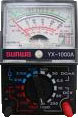
Analog multimeter
 In an analog multimeter, the measurement results are observed by the movement of the arrow (like on a clock) on a measuring scale on which the values are written: voltage, current, resistance. On many (especially Asian manufacturers) multimeters, the scale is not very conveniently implemented and for someone who first took such a device in his hand, measurement can cause some problems. The popularity of analog multimeters is explained by their availability and price ($ 2-3), and the main drawback is some error in the measurement results. For more accurate tuning in analog multimeters, there is a special tuning resistor, manipulating which you can achieve a little more accuracy. However, in cases where more accurate measurements are desired, the use of a digital multimeter is best.
Digital multimeter
 The main difference from analog is that the measurement results are displayed on a special screen (in older models using LEDs, in new ones on a liquid crystal display). In addition, digital multimeters have higher accuracy and are easy to use, since you do not have to understand all the intricacies of graduation of the measuring scale, as in arrow versions.
A little more about what is responsible for ..
Any multimeter has two outputs, black and red, and from two to four sockets (in old Russian even more). Black conclusion is common (mass). Red is called a potential conclusion and is used for measurements. The socket for general output is marked as com or simply (-) i.e. minus, and the conclusion itself at the end often has the so-called "crocodile", so that during measurement it can be hooked to the mass of the electronic circuit. The red pin is inserted into the socket marked with the symbols of resistance or volts (ft, V or +), if there are more than two sockets, then the rest are usually intended for the red pin when measuring current. Marked as A (ampere), mA (milliampere), 10A or 20A, respectively ..
The multimeter switch allows you to select one of several limits for measurements. For example, the simplest Chinese arrow tester:
-
Constant (DCV) and alternating (ACV) voltage: 10V, 50V, 250V, 1000V.
-
Current (mA): 0.5mA, 50mA, 500mA.
-
Resistance (indicated by an icon a bit like a headphone): X1K, X100, X10, which means multiplying by a certain value, in digital multimeters it is usually indicated as standard: 200Ω, 2kΩ, 20kΩ, 200kΩ, 2MΩ.
On digital multimeters, the measurement limits are usually larger, and additional functions are often added, such as sound diode ringing, transistor transition verification, frequency meter, capacitor capacitance measurement and temperature sensor.
In order to prevent the multimeter from failing when measuring voltage or current, especially if their value is unknown, it is advisable to set the switch to the maximum possible measurement limit, and only if the reading is too small, to obtain a more accurate result, switch the multimeter to the lower limit current.
Read more about the main criteria to consider when choosing a multimeter here: How to choose a multimeter
Start measuring
Check voltage, resistance, current
 It’s nowhere to measure voltage, if we set dcv as a constant, if acv as a variable, we connect probes and look at the result, if there is nothing on the screen, there is no voltage. With resistance it is just as easy, touch the probes to the two ends of the one whose resistance you need to find out, in the same way in the ohmmeter mode, the wires and paths are called for a break. Current measurements differ in that multimeter probes should be cut into the chain, as if it were one of the components of this very chain.
Resistor test
The resistor must be soldered out of the circuit at least at one end to make sure that no other circuit components will affect the result. We connect the probes to the two ends of the resistor and compare the readings of the ohmmeter with the value indicated on the resistor itself. The tolerance (possible deviations from the norm) should also be considered, i.e. if the marking is a resistor of 200 kOhm and a tolerance of ± 15%, its actual resistance can be in the range of 170-230 kOhm. With more serious deviations, the resistor is considered faulty.
Checking the variable resistors, we first measure the resistance between the extreme terminals (it should correspond to the resistor value), and then connecting the multimeter probe to the middle terminal, alternately with each of the extreme ones. When the axis of the variable resistor rotates, the resistance should change smoothly, from zero to its maximum value, in this case it is more convenient to use an analog multimeter while observing the movement of the arrow than for rapidly changing numbers on the LCD screen.
Diode test
If there is a function for checking diodes, then everything is simple, we connect the probes, the diode rings in one direction, but not in the other. If this function does not exist, set the switch to 1 kOhm in the resistance measurement mode and check the diode. When you connect the red output of the multimeter to the anode of the diode, and the black to the cathode, you will see its direct resistance, when you reconnect, the resistance will be so high that you will not see anything at this measurement limit. If the diode is broken, its resistance in any direction will be zero, if it is cut off, then in any direction the resistance will be infinitely large.
Capacitor Test
It is best to use special instruments to test capacitors, but a conventional analog multimeter can help. A breakdown of the capacitor is easily detected by checking the resistance between its terminals, in which case it will be zero, more difficult with an increased leakage of the capacitor.
When connected in the ohmmeter mode to the terminals of the electrolytic capacitor, observing the polarity (plus to pluses, munus to minus), the internal circuits of the device charge the capacitor, while the arrow slowly creeps upward, indicating an increase in resistance. The higher the capacitor rating, the slower the arrow moves. When it practically stops, we change the polarity and observe how the arrow returns to the zero position. If something is wrong, there is most likely a leak and the capacitor is not suitable for further use. It is worth practicing, because, only with a certain practice you can’t make a mistake.
Transistor test
Conventional Bipolar Transistor represents two diodes connected towards one another. Knowing how diodes are checked, it is not difficult to check such a transistor. It is worth considering that transistors are of different types, p-n-p when their conditional diodes are connected by cathodes, and n-p-n when they are connected by anodes. To measure the direct resistance of transistor p-n-p junctions, minus the multimeter is connected to the base, and plus alternately to the collector and emitter. When measuring the inverse resistance, we reverse the polarity. To test transistors of n-p-n type, we do the opposite. If even shorter, then the base-collector and base-emitter junctions must be dialed in one direction and not in the other.
For more information on how to check transistors, see here.

And a couple of tips in the end
When using a pointer multimeter, lay it on a horizontal surface, as in other positions the accuracy of the readings may noticeably deteriorate. Do not forget to calibrate the device, just close the probes between each other and a variable resistor (potentiometer), make sure that the arrow looks exactly at zero. Do not leave the multimeter on, even if there is no position on the analog device on the switch - off. do not leave it in ohmmeter mode, since in this mode the battery power is constantly lost, it is better to put the switch on the voltage measurement.
In general, while this is all I wanted to say, I think that beginners will have no more questions about this, but in general there are so many subtleties in this matter that it is simply impossible to tell about everything. For the most part this is not even taught. It comes by itself. And only with practice. So, practice, measure, test and each time your knowledge will be stronger, and you will see the benefit from this already at the next malfunction. Just do not forget about safety precautions, just as high currents and high voltages can cause trouble!
See also on this topic: Arrow and digital multimeters - advantages and disadvantages andHow to use a multimeter
See also at e.imadeself.com
: