Categories: Electrician at home, Electric installation work
Number of views: 85661
Comments on the article: 6
How to assemble the electrical panel
The massive construction of the housing stock and the ongoing reconstruction of old buildings push apartment owners to the need to independently understand the technologies for performing electrical work in their premises. This allows you to create an individual electrical system that meets the specific needs of the owner, rather than using a typical circuit designed for the average consumer.
How to choose the location of the electrical panel
To properly assemble the electrical panel in a newly built apartment, it is necessary to draw up projectin which it is necessary to provide for the detailed implementation of their needs inside each room, to consider the location of lamps and switches for them, the number of sockets for portable and stationary electrical appliances.
At the same time as electric wires, it is often necessary to lay pipelines for water supply, heating, telephone lines, antenna cables, a computer network, intercom, alarm and other low current circuits. Route optimization of all these systems is just part of the project development.
The electrical panel is the place where the cable coming from the energy supplying organization is connected to the electricity meter for further distribution of electricity to the consumers of the apartment through switching machines.
The objective of the project is to determine the most suitable location for the input electrical panel. Recently, it is customary to install it not on the landing, as was done in the last century, but inside the apartment. This eliminates unauthorized access to equipment and creates certain amenities.
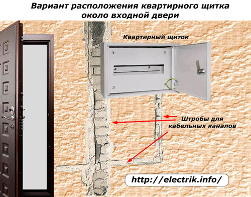
Typically, the location of the shield is chosen in the corridor near the front door at a height of the face level because it is so convenient for residents take meter readings and disconnect unnecessary consumers when leaving the apartment. And during installation, the length of the power cable is reduced.

When choosing a location for the shield, the owners of the cottage and private house should take into account the safe organization of the input device into the building, the design of the branch from the overhead power line or cable line, and coordinate their device with the power supply organization.
How to choose the design of the electrical panel
In residential buildings, two types of wiring are used:
-
external laid on the surface of the walls;
-
internal, hidden in gates and cavities.
Under them are issued electrical panels that can simply be attached to the outside of the wall or mounted inside it, making an appropriate recess.
The material of the flap box is designed for a long service life. It may be:
-
metal;
-
strong plastic.
External and internal decorative finishes, made in various shades of color, allows you to make a quality choice for the design of any room.
Responsible devices are located inside the shield. Access to them by unauthorized persons and children should be limited by closing the door with a lock, the key of which must be stored in a separate place. To monitor the counter, it is enough to have a window on the door.
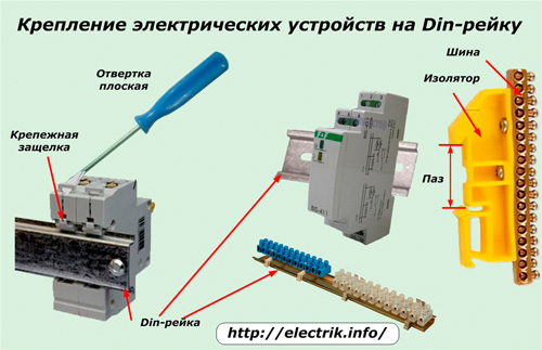
The practical majority of modern shields are available for convenient and reliable placement of electrical devices on Din rail. Such designs should be used. They significantly save space and make it easy to dismantle a faulty device.
To fix the machine, it is enough to put it with the rear groove to the rail, use a screwdriver to pull out the fastening latch, press the housing slightly and release the lock. Removal is performed in the reverse order.

Din rail can be mounted terminal blocks and tire assemblies in various ways.
From the point of view of an electrician, it is necessary to choose an electrical panel in terms of dimensions for placement inside all the required switching devices, protective devices, metering and control devices. Therefore, before visiting the store, it is important to complete the creation of the wiring project and decide on all electrical appliances that should be placed inside.
In addition, practice has shown that modern people are constantly acquiring a variety of electrical equipment, and for it it is necessary to create additional power lines. Sometimes the owners even had to deliver a second switchboard next to the main one. Therefore, when choosing a design, it is always recommended to create a reserve of internal space.
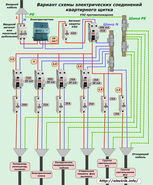
An approximate diagram of the selection and connection of switching devices and protections for placement inside the shield housing is shown in the figure. The composition of component parts in each individual case may vary significantly.
Here it is shown that the voltage from the access panel is supplied by a power cable with three cores:
1. L is the phase of the network;
2. N is the working zero;
3. PE - protective conductor.
For clarity, each of them is highlighted in its own color: red, blue and yellow-green, which are used in practice to denote wires.
Phase and zero wires are connected to the input circuit breaker or batch switch (switch), and the protective PE conductor is immediately sent to its bus. With it, he divorces all consumers with veins of outgoing cables.
From the introductory machine, the voltage is supplied to the meter and after it - further into the circuit. The picture shows that for this chain copper wires with a cross section of 10 mm square are used, which will absorb the maximum load of all connected devices. It should be noted that access to the terminal block of the meter and the contacts of the input circuit breaker after the installation is completed will be sealed by the energy supervision representative.
After the electric meter, a fire-protective RCD is installed with a setpoint for a leakage of 300 mA and the rated current of the electrical circuit. Since the residual current device can burn out from short-circuit currents, it is protected by a circuit breaker of the appropriate rating.
In the above diagram, this switch duplicates the input automaton, so you can not put it here. But it will be needed if a switch or switch is used.
The working zero after exiting the fire protection RCD is connected to its bus, and from it it is bred to consumers. When RCDs or differential machines are installed on the lines, the neutral wire is passed through them.
As an example, it is shown that all electric consumers of the apartment are divided by the project into six lines. It is important to observe the principle of not only their territorial association, but also the distribution of load power. So, the electric stove is connected by a separate line with 4 mm square conductors, and a 32 amp circuit breaker.
A television, a computer, a socket for portable electrical appliances can be combined into one chain, made with 2.5 mm square wires and powered from a 20 amp machine. In the same way do with other consumers.
In all electrical devices, which can be touched by a person, an RCD or differential automata. The diagram shows that in order to save money, they were abandoned in lighting chains.
Each RCD controls a specific section of the circuit. It can include several consumers. This will save space in the shield and money. But when the RCD trips, it will be necessary to look for its cause - the place of violation of isolation.
The more devices connected in the chain, the more difficult it is to identify the location of the malfunction. It is quite possible that leakage currents through each device are not dangerous, and their total value exceeds the set point.
Also in the above example is missing voltage monitoring relay, which is intended to protect electrical equipment from cases of increasing voltage in the wiring of 0.4 kV at burn-out or breakage of the neutral conductor. Automatic removal of power from the circuit when such an emergency occurs by means of an ILV saves household appliances and ensures peace of mind for the owners.
The voltage control relay is installed immediately after the electric meter to the fire protection device.
It is very important to correctly connect the RCD in the electrical panel: The correct circuit for connecting an RCD
How to carry out internal installation
The sore spot of most non-professionally assembled circuits is a continuous ball of mixed wires, which is difficult for even good specialists to understand. Internal installation must be thought out in advance.
To do this, it is advisable to start the lead-in cable on its side from above or from the side, and the outgoing cables from the opposite. This technique also saves on cable length.
When mounting, it is advisable to adhere to color coresgiven as an example for an input cable. When this is not possible, then the endings of the cores are signed with a non-fading marker or black ink based on dichloroethane.
Tires for working and protective zero are located on the side, providing free access to them. The use of special designs of terminal blocks for tires in the housing facilitates installation, makes it more understandable.
When instead of an RCD with a circuit breaker, a differential machine is used, then the working zero after it is output directly to the load cable, and not to the busbar. Otherwise, the algorithm of the difavtomat will be changed, the circuit will work incorrectly.
The design of circuit breakers requires their installation in a vertical position with input contacts from above. With a different location, they work, but their resource is reduced. Only well-known brands of companies such as Siemens or Legrand allow arbitrary orientation of expensive models of their products.
Connecting the incoming wires to the machines is performed on the upper contacts, and the outgoing circuits on the lower ones. This is customary according to the etiquette of electricians: facilitating the search for emerging faults inside the circuit.
In addition, in the designs of most machines, the fixed contacts are located on top. Arcing devices and a movable contact part are placed near them. The passage of current from the bottom up can cause energy loss.
In any case, the main principle of installation should be the complete uniformity of the methods of connecting conductors on all elements inside the shield body.
Only one core is allowed per terminal. A larger amount can weaken the electrical contact over time, so it is prohibited by the rules.
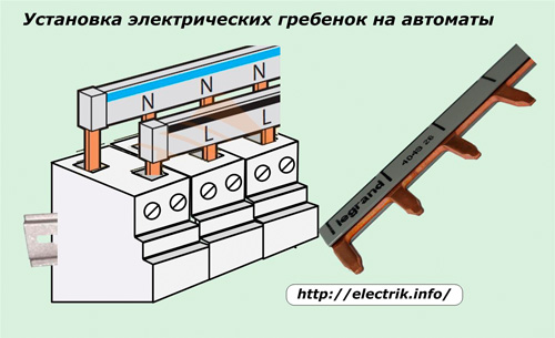
To connect automatic machines to each other, many electricians make jumpers. Aesthetic appearance and reliable connection provide electric combsmanufactured by manufacturers of circuit breakers. They speed up installation, save space for wires.

All work inside the shield is carried out according to the approved electrical connection diagram, a copy of which must always be at hand. Often it can be conveniently glued to the door from the inside. In this case, all mounting connections of the circuit are transferred by marking to existing equipment.
Each element of a working scheme must be signed so that its purpose is clear even with a cursory glance. To do this, you can type text on a computer and print small explanatory labels on the printer.
When there is no place for such labels, a bright digital designation is applied to all equipment, and an explanatory table with a detailed interpretation of the necessary information is glued to the door. It is convenient to store such a leaf near the electrical panel.
Detailed documentation, clear labeling and intuitive installation increase the reliability of the operation of electrical equipment, give the electrical panel an aesthetic appearance, and provide quick troubleshooting.
After the completion of installation work, an inspection of all installed equipment is mandatory, the places of electrical connections and fastening of the elements are compressed, the installation is carried out correctly and insulation resistance fully assembled chains. Only after this, trial inclusion under load and testing in operation is allowed.
During operation, it is necessary to carry out periodic preventive examinations and checking the condition of threaded connections in the terminals. This will guarantee a reliable operation for a long time.
See also at e.imadeself.com
:

