Categories: Featured Articles » Electrician at home
Number of views: 53449
Comments on the article: 10
Grounding device for a country house
 Device need re-grounding at the entrance to the country house is dictated by the current rules of the PUE. In accordance with paragraph 1.7.61 of these rules at the input to any electrical installation grounding systems TN installation of a grounding device with a current spreading resistance of 30 ohms for a three-phase network and 60 ohms for a single-phase network is recommended. These recommendations can only be neglected if available and used. natural grounding (metal structures partially located in the ground and meeting the requirements of the PUE for resistance).
Since it is far from always possible to choose a suitable natural grounding conductor, the device of a separate grounding device (charger) at the entrance to the newly built country house becomes the most rational technical solution. Moreover, it does not require special material costs.
Grounding device includes a grounding conductor, as well as a grounding conductor located directly in the ground. Ground conductor - a conductive conductor connecting the PE bus (main grounding bus, or GZSh) to the ground electrode. The cross section of this conductor is normalized by table 1.7.5 of the EIC and depends on the cross section of the phase conductors.
So, if the phase lead-in conductor has a cross section of 16 square meters. mm or less, the ground conductor must have a cross section equal to or greater than the cross section of the phase conductor. With a larger cross section of the phase input conductor, the ground conductor may have a cross section equal to half the cross section of the phase conductor.
Of course, we are talking about those cases when the materials of the phase and ground conductors coincide. If this is not so, then it is necessary to take into account the difference in the resistivity of the conductive materials. It is possible to use grounding conductors having a cross section less than recommended by table 1.7.5 (see PUE), but only if a calculation is made confirming that mains short circuit current will be of sufficient size to trigger protection.
For the installation of grounding conductors, preference is usually given to multi-wire copper wires in single-yellow polyvinyl chloride insulation (yellow-green) (PV-3) Grounding conductor on the earthing side crimped with cable lug and sits on a steel bolt, and from the side of the GZSH it is fastened either under a clamp with preliminary tinning, or again with a bolt and a tip - depending on the design of the tire itself.
The earthing switch is structurally composed of horizontal conductorslaid in the ground and directly vertical grounding electrodes. The material of both those and others may be different.
In accordance with the technical circular No. 11/2006 from the Roselectromontazh Association, which clarifies and supplements the PUE standards, bringing them into line with international standards, it is allowed to make earthing switches from black steel, steel with various types of coating, from tinned or galvanized copper, or from copper without any coating.
The cross-sectional shape of the grounding electrodes and conductors laid in the ground may also be different. It can be a corner, strip, pipe, bar. For each of these sections, the minimum size and minimum dimensions in any direction are normalized. So, for example, the use of a black steel strip thinner than 5 mm is excluded, even if its cross-sectional area is normal and is at least 150 square meters. mm These limitations are related to the corrosion resistance of the ground electrode material.
The grounding conductors are connected either by weldingor bolted. Other connection methods are not allowed.
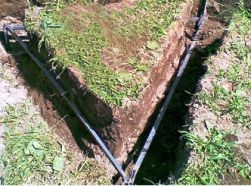
The most popular technical solution for the earthing device is the vertical installation in the ground of three steel bars with a diameter of 18 mm and a length of 2.5-3 meters, connected by a steel strip of 40 * 5 mm. The bars are located at the vertices of an imaginary equilateral triangle. This whole structure is located at a depth of 0.5 meters underground.
To make the conclusion necessary for connecting the grounding conductor, you can use the same strip welded to the grounding and displayed on the wall of the house in any convenient place.
Upon completion of work related to the device for re-grounding at the entrance to the house, it is necessary to invite specialists from a registered electrical laboratory to take measurements and issue a protocol confirming the fact that the electrical resistance of the ground electrode is within normal limits.
Alexander Molokov
See also at e.imadeself.com
:
