Categories: Electrician at home, How does it work, Sockets and switches
Number of views: 307,520
Comments on the article: 22
Dimmer device and circuit
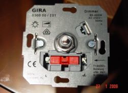 In this article, we will consider a device that is sold in electrical goods stores as a dimmer control. It's about a dimmer. Title "Dimmer" came from the English verb "to dim" - to darken, become dull. In other words, the dimmer can be adjusted lamp brightness. Moreover, it is remarkable that the power consumption decreases proportionally.
The simplest dimmers have one rotary knob for adjustment, and two terminals for connection, and are used to adjust the brightness of incandescent and halogen lamps. Recently, dimmers have also appeared to adjust the brightness of fluorescent lamps.
Previously, rheostats whose power was not less than the load power were used to adjust the brightness of incandescent lamps. Moreover, with a decrease in brightness, the remaining power was not saved in any way, but was dissipated uselessly in the form of heat on a rheostat. At the same time, no one spoke about saving, it simply did not exist. And such devices were used where it really was only necessary to adjust the brightness - for example, in theaters.
So it was before the advent of wonderful semiconductor devices - a dinistor and a triac (symmetric thyristor). See: How the simistor is arranged and works. In English practice, other names are accepted - diac and triac. Based on these details and work modern dimmers.
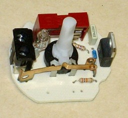
Dimmer connection
The circuit for switching on the dimmer is impossibly simple - you can’t imagine any easier way. It turns on in the same way as a conventional switch - into the open circuit of the load supply, that is, the lamp. In terms of installation dimensions and mounting, the dimmer is identical to the switch. Therefore, it can be installed in the same way as a switch in a mounting box, and the installation of a dimmer is no different from the installation of a conventional switch (How to replace the light switch) The only condition that the manufacturer makes is to observe the connection of the leads to the phase and to the load.
All the dimmers that are currently on sale can be divided into 2 groups - rotary, or rotary (with a regulator - potentiometer) and electronic, or push-button, with buttons.
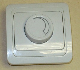
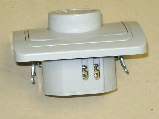
Rotary dimmer
When adjusting (dimming) the potentiometer knob, the brightness depends on the angle of rotation. The push-button dimmer in the sense of control flexibility is more flexible. You can connect several buttons in parallel, and control the dimmer from any number of places. Of course, this is theoretically, in practice, the number of control places is limited to 3-4, and the maximum length of wires is about 10 meters, and the circuit can be critical to interference and interference. Therefore, we must strictly follow the manufacturer's recommendations for installation.
There are also remote dimmers controlled via radio or infrared. See: Remote lighting control.
The price for dimmers with a regulator and buttons differs by an order of magnitude, because a button dimmer (for example, a Legrand dimmer) is usually assembled with microcontroller application. Therefore, rotary dimmers are much more common, which we will consider below.
The device and circuit rotary dimmer
The rotary dimmer device is very simple, but may differ from different manufacturers. In this case, the main difference is in the quality of assembly and components.
The circuit of triac regulators is basically the same everywhere, it differs only in the presence of additional parts for more stable operation at low "output" voltages and for smooth regulation.
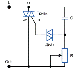
Simplified Dimmer Circuit
The principle of operation of the dimmer circuit is as follows. For the lamp to light up, it is necessary for the triac to pass a current through itself. This will happen when a certain voltage appears between the electrodes of the triac A1 and G. This is how it appears.
At the beginning of the positive half-wave, the capacitor begins to charge through the potentiometer R. It is clear that the charge speed depends on the value of R. In other words, the potentiometer changes the phase angle. When the voltage across the capacitor reaches a value sufficient to open the triac and dinistor, the triac opens.
In other words, its resistance becomes very small, and the bulb burns to the end of the half-wave. The same thing happens with the negative half-wave, since the diac and triac are symmetrical devices, and they do not care which way the current flows through them.
As a result, it turns out that the voltage at the active load is a "cutoff" of negative and positive half-waves, which follow each other with a frequency of 100 Hz. At low brightness, when the lamp is powered by very short “pieces” of voltage, flicker is noticeable. What can not be said about rheostatic regulators and regulators with frequency conversion.
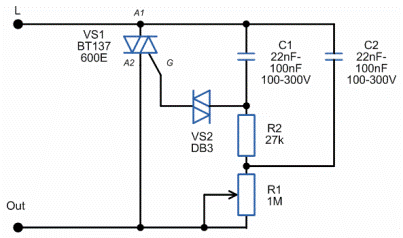
Rotary Dimmer Circuit
It looks like this real scheme of the dimmer. The parameters of the elements are indicated taking into account the scatter of different manufacturers, but the essence of this does not change. Triacs in a practical circuit can be set any, depending on the load power. Voltage - not lower than 400 V, since the instantaneous voltage in the network can reach 350 V.
From the size of the capacitors and resistors depends on the starting-end point of ignition, the stability of the lamp. With a minimum resistance of the rotary resistor R1 there will be minimal lamp burning.
With a strong desire, you can try to make a dimmer yourself. There are a large number of different schemes of homemade dimmers of different levels of complexity. You can learn more about homemade dimmer circuits in a series of articles by Boris Aladyshkin about homemade dimmers - How to make a dimmer yourself.
How to repair a dimmer
In conclusion - a few words about the repair of dimmers. Most often, the cause of the breakdown may be an excess of the maximum permissible load or a short circuit in the load. As a result, as a rule, the triac fails. The triac can be replaced by unscrewing the radiator and dropping the triac from the board. It is better to immediately put a powerful one at a higher current and voltage than a burned one. It also happens that the regulator fails, or the installation is broken.
The dimmer can be used as a voltage regulator, connecting any active load through it - an incandescent lamp, soldering iron, kettle, iron. But most importantly - the power of the dimmer (in other words, the maximum current of the triac) should correspond to the load.
See also at e.imadeself.com
:
