Categories: Featured Articles » Home automation
Number of views: 25843
Comments on the article: 7
Application of a frequency converter and voltage regulator in suburban water supply systems
 This article discusses the use of a frequency converter and a voltage regulator to solve the problem of managing a suburban water supply system. The article is a continuation of the article. “Voltage regulator for smooth regulation of power at the load”, which describes what a "voltage regulator" is, a design is considered, connection diagrams are given.
As an object of automation, a house was selected in a suburban cottage village, connected to a central water supply. The main drawback of the central water supply system in the village is the inconsistency of water pressure, in a very wide range of 0.5-1.8 atm., Which by itself is not enough to comfortably take a shower or to water the entire garden at the same time.
The customer was asked to modernize the current water supply system, to make an effective system for regulating the outlet pressure in the cottage and to automate the irrigation system of the personal plot. The following conditions were put forward as a task:
-
the output pressure level in the cottage should be continuously adjustable in the range from 2.0 to 4.0 atm .;
-
water pressure should be stable and should not depend on the flow of water in the cottage and on the level of inlet pressure;
-
protection against dry running of the pump should be provided;
-
irrigation system should automatically provide water for up to 6 sprinklers distributed throughout the site;
-
the system should be able to parameterize and control from a portable touch panel over the air;
-
the possibility of remote monitoring and control via the Internet should be provided;
-
the system should provide energy and resource saving;
IN In general, the system can be divided into three parts:
-
water supply system and stabilization of the outlet pressure level;
-
site watering system;
-
monitoring and control system, including remote.
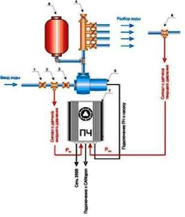
The water supply and output pressure stabilization system is shown in Figure 1. It uses a centrifugal pump (5), which increases the pressure at the system outlet (Ptek) with the required water flow rate and a changing value of the inlet pressure (Pin). The system also consists of a valve supplying water (1), an analog input sensor (2) and output (6) pressure, a check valve (3), control valves (4), a hydraulic accumulator (8) and a frequency converter (IF) (7) , which makes possible the operation of the pump motor at different speeds.
Fig. 1. Water supply and pressure regulation (click on the picture to enlarge)
The signals coming from the input and output pressure sensors are entered directly into the inverter via the analog input module. The pressure control software is flashed to the inverter; in general, it can function without additional peripherals. However, in our case, all private facilities are combined into a single network with a radio-controlled remote control with a touch panel, to improve the efficiency and convenience of controlling the entire system.
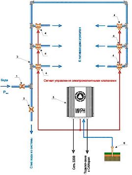
The irrigation system is shown in Figure 2. It is specially designed for Russian operating conditions, as simple and convenient as possible. The system consists of a summer water supply (3), laid along the entire site. Through solenoid solenoid valves (4) water through flexible hoses flows to conventional portable irrigation systems. In total, the system uses 6 solenoid valves and flexible hoses. For the “winter” shutdown, the valves for water supply (1) and drain (2) are used. Solenoid valves are controlled by a multi-channel intelligent voltage regulator (MIRN) (5) from AC power.
Software and watering algorithms are wired directly at MIRN and can work autonomously. As in the previous case, all systems are combined into a single network with a remote control. To calculate the level of soil moisture in the system, analog humidity sensor (6). It is connected to the MIRN through the analog input module and is necessary for the correct determination of the duration and volume of water required for watering the site.
Fig. 2. Watering system (click on the picture to enlarge)
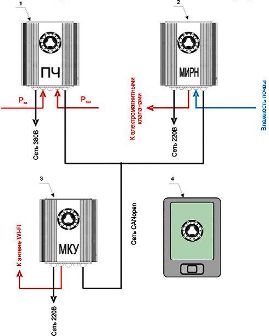
The general scheme of the monitoring and control system is shown in Figure 3. The figure shows all the devices embedded in the control system: a frequency converter (IF) (1), a multi-channel intelligent voltage regulator (MIRN) (2), a microcontroller control (MCU) (3) and remote control (4). IF, MIRN and MKU are integrated into a CAN network.
Fig. 3. Monitoring and control system (click on the picture to enlarge)
MKU is used to control and distribute tasks to the controllers responsible for water supply (in the inverter) and irrigation (in MIRN), as well as for input-output of the necessary information to the control panel via the WI-FI wireless network. The remote control works through the WEB interface with control over the Internet and can be moved to anywhere. As a remote control, a conventional touchscreen tablet computer with an integrated WI-FI module was used.
I especially want to note that when implementing this system, resource and energy-saving technologies were applied. MKU with a real-time clock module (RTC) has “day-night” modes. There are special modes "no owner" and "save water."
The use of an inverter to control a water circulation pump made it possible to eliminate inrush currents when starting the engine and to stabilize the value of the water pressure in a country house at different input pressures and water flow rates. This solution allowed to save 40% of water and 60% of electric power in comparison with a traditional way of management.
Klyuev Pavel
Read here how to do it.do-it-yourself frequency converter
See also at e.imadeself.com
:


