Categories: Microcontroller circuits
Number of views: 33735
Comments on the article: 2
19 shields for Arduino for all occasions
Shield is a supplement board. I propose to divide the shields into full-size and separate modules. Full-sized with their outlines, they repeat the shape of the Arduino board, whether it be UNO, Nano or MEGA. Separate modules are free-form cards designed to perform a specific set of functions. Both that and others can be both universal, and for performance of narrowly targeted tasks.
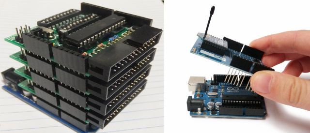
In stores you can find a great many shields, and with a certain qualification you yourself can breed a printed circuit board that repeats the arduine in the shape and location of the terminals and assemble your own unique one. The picture shows Arduino UNO Board with a set of shields.
Universal board for easy prototyping
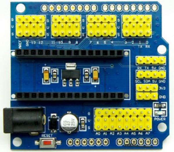
Let's start with the shield, which does not carry any special functions, but was created for the convenience of installing your projects. So, the first in our review will facilitate the installation of projects with the Arduino Nano board, although the sense of the small size of "NANO" in this case is zero.
On the board there is a connector for connecting the plug from the power supply unit, a voltage stabilizer, as well as terminal blocks. They are signed and are consistent with the findings of Nanki. In addition, there is a reset button and a Power LED.
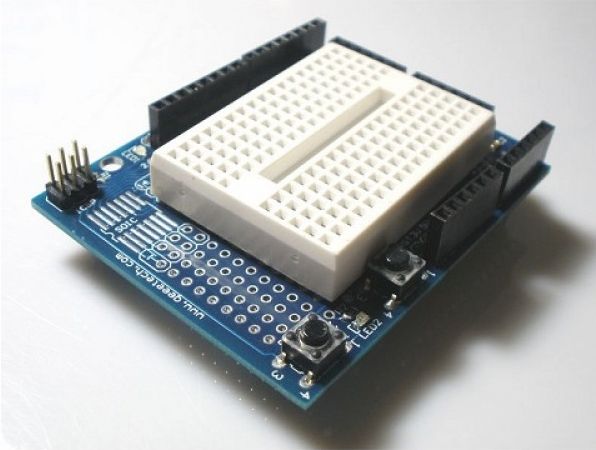
The second shield is for the Uno board. It contains a solderless breadboard for assembling the project and conclusions that duplicate those on the arduino itself - a convenient solution.
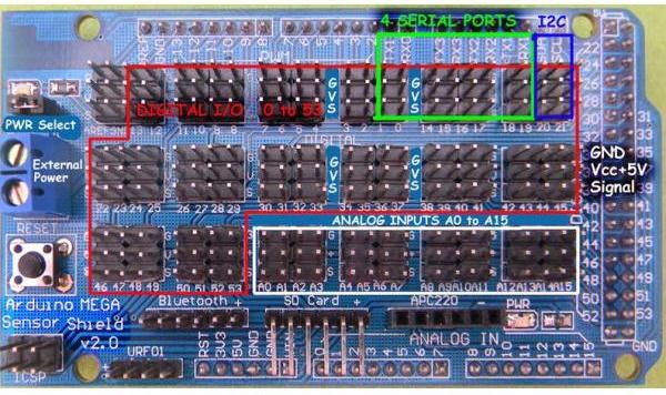
Any analog sensor needs power and negative contact, when there are a lot of them - there are so many jumpers that it will be very difficult to understand the circuit. Therefore, designers came up with shields for such solutions. All the inputs and outputs are displayed in them, and the supply contacts are duplicated and placed side by side.
Here is an example of such a board for the Arduino Mega version.
Wired and wireless
Using these boards, you can organize microcontroller control over the network via an Ethernet cable, for example, or wirelessly via GSM-connection by inserting a SIM card.
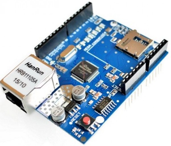
This board is called w5100 - it contains an Ethernet module and an SD card reader module. This means that you can store data, for example, a log of sensor measurements on a memory card and control the system through a web interface. To associate an arduino with it, use the libraries:
-
Ethernet library;
-
SD library.
Pay attention externally, he repeats the concept of Arduino UNO R3, in addition, it is suitable for Mega.
If the W5100 seems too large to you, then the ENC28J60 will take up less space. Unfortunately, it no longer has an SD module.
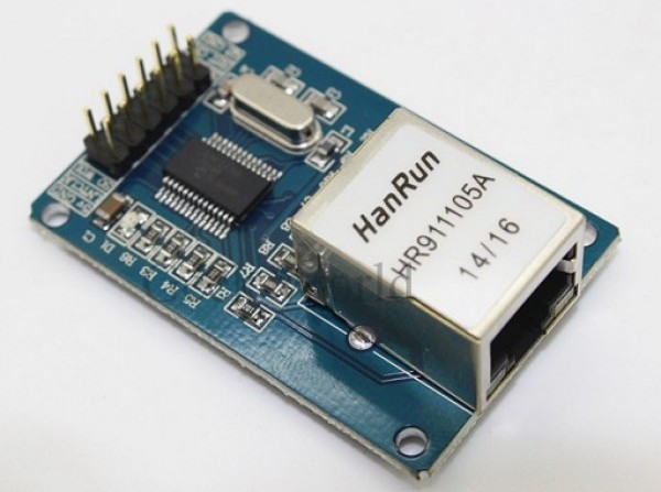
The downside is that it cannot be mounted on a board, but is designed as a separate module.
The W5500 is another version of the Ethernet shield. At its core, this is a revised version of the W5100, optimized in terms of speed and energy efficiency.
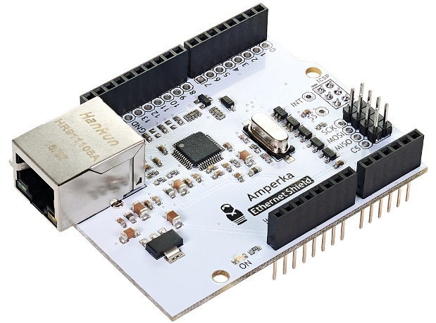
Please note that on full-sized shields, all pins are duplicated by the terminal block. Unfortunately, shields use ports. Specifically, this uses MOSI, MISO, SCK, and pin 10, for the CS signal (select a destination for communication).
If you need wireless connection, your choice is Wi-fi shields, if you have Internet and a router, and if not, GSM-modules or GPRS Shields.
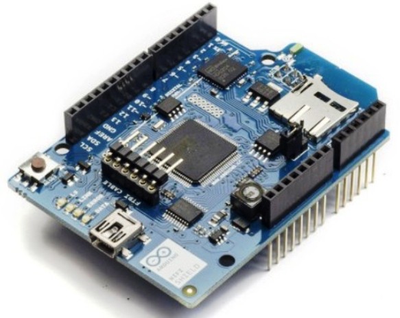
On the photo is the official shield. A slot for a Micro SD memory card is installed on it, and it communicates with the microcontroller via SPI protocols, through Mini-USB you can update its software. Supports 802.11b / g.
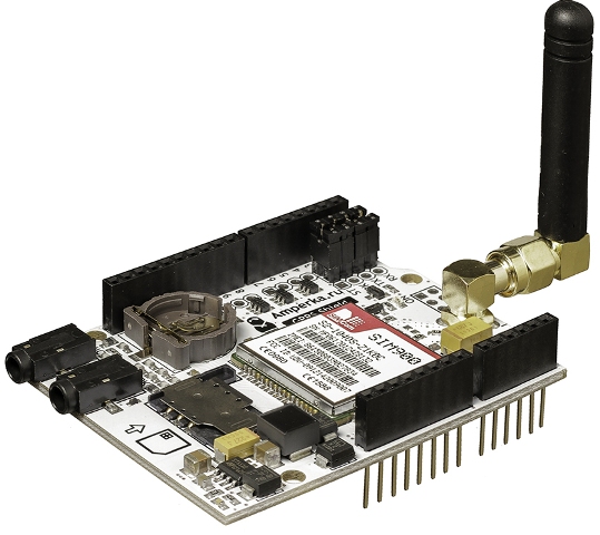
The GPRS shield from Amperka you see above. You can replace the antenna with a more powerful one. Closer to the viewer you can see the SIM card slot, a little further on the CR1225 battery slot. The battery on the board is needed for real-time hot hours, and this is an important addition to the capabilities of the GPRS shield. You can send SMS to and from him.
With this board you can control and give commands to your smart home (or any other project of your implementation) being at any distance. It is important that you are in a cellular coverage area.
How to store data on Arduino?
In projects, not all information is placed in the memory of the microcontroller. Sometimes you need to store some amounts of information. The first thing that comes to mind has already been said is the recording of information from sensors in order to further study how the environment changes over the course of hours, days, years. A great example is a home weather station. This is useful not only for scientific researchers, but also amateurs for general education and development.
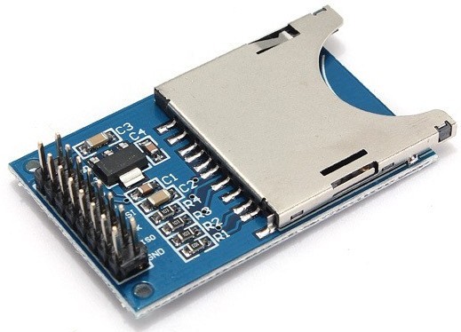
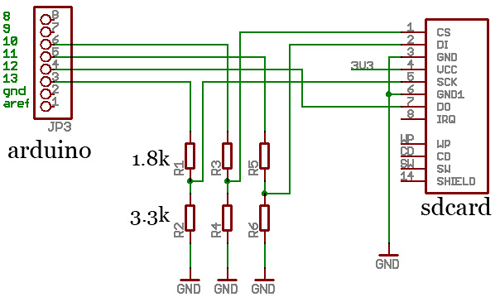
It is rather not a shield, but a module. It is miniature and easy to repeat, by the way, here is its outline.
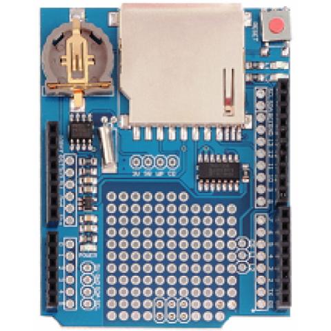
There is also a full-size data storage shield. It works with SD-memory cards, there is a real-time clock module on board that is powered by a 3 V CR1220 battery, which is a good bonus.
We manage a powerful load from the microcontroller
The first thing that comes to mind is a relay. With their help, you can switch both DC circuits and with a 220 Volt household power supply they can cope with a bang.
Specifically, the module that is shown below can switch 1 kW 220 V of the load (or 5A) for each channel, to increase power, you can either parallelize several channels, or turn on this relay magnetic switch. In this case, the relays from the shield will play the role of intermediate amplifiers.
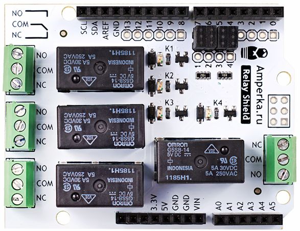
Of course, you can switch the relay as I described in the article “Connecting external devices to Arduino”, through the transistor and you need to select the current relay, but using the finished board will be more reliable, more convenient and looks better.
The relay has one drawback - a limited number of trips - this is a consequence of contact burnout. This happens due to the appearance of an arc, when a powerful load is opened (especially an inductive character - this is an engine, etc.). You can make such a shield according to the following scheme:
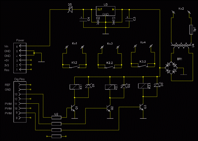
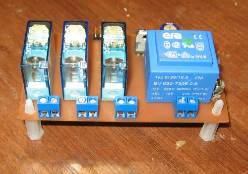
And here is how it looks in the assembly:
You can use thyristors and triacs to turn on an AC load. One problem is that they cannot be connected directly to the arduino, in case of breakdown of the pn junction of the control electrode, 220 V can be on the microcontroller board and burn it. The way out of this situation is the use of an optosimistor.
Since this task often arises before inventors, a turnkey solution was developed - triac shield, its full name is ICStation 8 Channel EL Escudo Dos Shield for Arduino. It was originally intended to control the glow of "flexible neon."
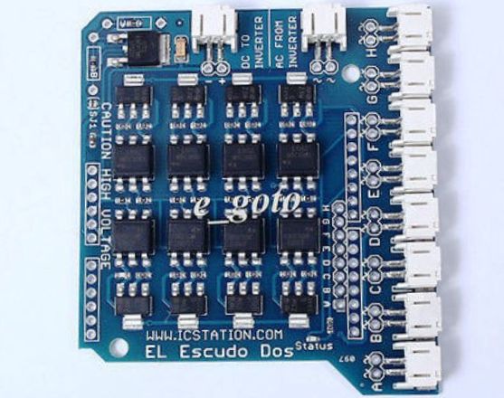
It has 8 channels to which the AC network and load are connected.
Shields for engines
Motor control is not always an easy process. In some situations, you may not have enough pins to implement the task, or the control algorithm is quite complicated. With such boards, you will be able to defeat the design of your robot much faster.
Motor-SHILD for arduino can control DC motors (4 pieces) or two stepper motors.
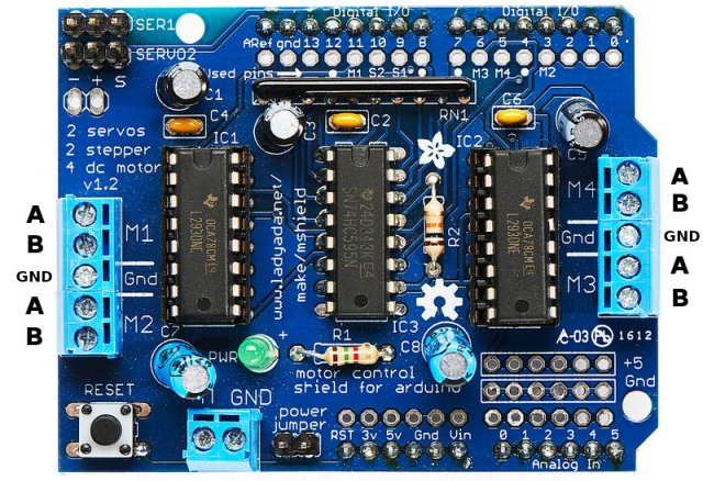
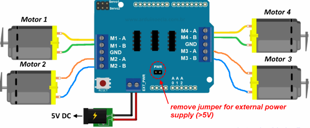
It is built on the basis of two L293. This microcircuit is an assembly of two H bridges, this allows you to control with the possibility of reverse two DPT, or 1 step bipolar motor. Connection diagrams respectively:
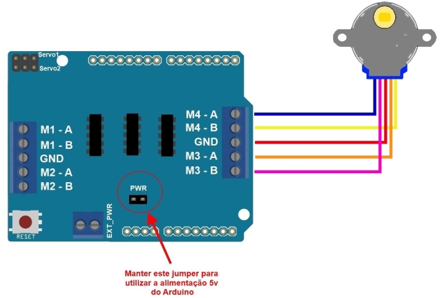
And in the upper left corner of the board there are two pads for servos (plus, minus and control signal). The red circle circled the place where the jumper jumper is installed. If it is, then this board is powered by an arduino baseboard, and if not, from an external source of 5 V.
Using this module from a domestic manufacturer, you can control two DC motors, it also has a jumper that combines the power supply lines of the microcontroller or disconnects them for power from a separate source.
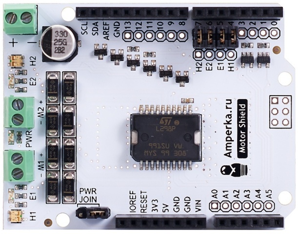
You can control motors that are designed for a voltage range of 5 to 24 volts. Instead of 2 DC motors, you can use 1 single-phase stepper or parallelize the channels and connect 1 powerful DC motor with a current of up to 4A, and this is not enough - 48 W with a supply voltage of 24 V.
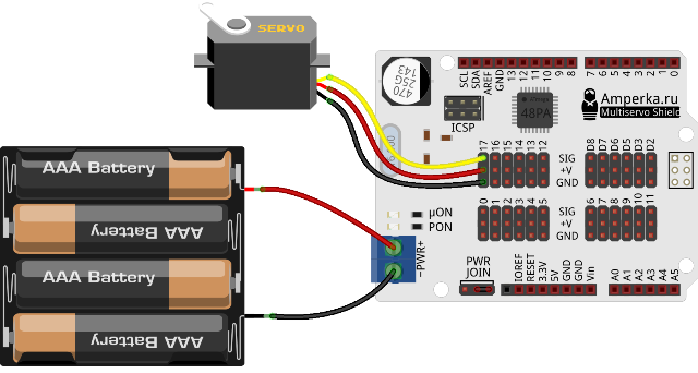
To connect a servo, you need three wires - plus, minus and signal, but what if you have a lot of serv? Your board will turn into a mess of jumpers. To avoid this, there is a Multiservo shield.
Here, too, there is the possibility of separation of power circuits, as was the case in the previous version. In total, you can connect 18 servos (on the board numbering from 0 to 17).
Everywhere has its own specifics, shields for unusual tasks ...
Atmega 328, the heart of our board, is the ADC. The main problem is that on the Arduino Uno board we see only 6 analog inputs. What if we have more analog sensors?
You can collect two arduino in a single network. One of them should be used as the main one, and the second one for changes and from the first one to send measurement signals to the server or display them on the screen ... But this is difficult: you need to spend memory on additional lines of program code to implement such a system.
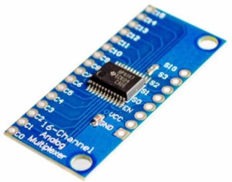
But what if you multiply each input by 16? Total we can have up to 16 * 6 = 96 analog inputs. This is real with a multiplexer. It simply switches 16 analog channels in turn to one analog output, which you connect to the same input of any microcontroller.
Voice recognition
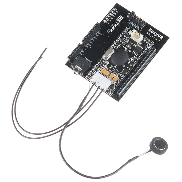
By means of the Atmega microcontroller, it is very difficult to release the voice recognition function, but arduinists can not despair, there is a special solution - EasyVR Shield 3.0.
This is a ready-made, but expensive solution, at the time of writing, it costs almost $ 100 in Russia. First, the shield will write down your command, then compare it with what is written in memory, having determined the number, it will execute it.
You can arrange a “dialogue with the computer”, it can reproduce what is written in it. Without additional amplifiers, it is recommended to "communicate" with this board from a distance of not more than 60 cm.
Display image
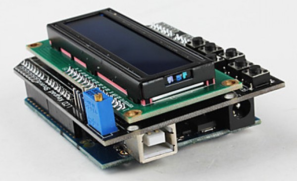
LCD Keypad shield is a real control panel. On it is the LCD1602 display (16 characters in two lines), and a set of buttons. Because of them, quite a few ports are involved, for example, A0 and from D4 to D7 under the keyboard, and port D10 is a PWM dimmer control. D8 and D9 - reset and inclusion.
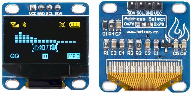
In fact, there are many displays compatible with arduino. Rather, those about which the most information is written and you can easily run them in your system. The display from NOKIA 5110 is quite popular in DIY circles, there are also OLED and TFT screens working on I2C to choose from. But they are not in the "shield" version.
Autonomous food
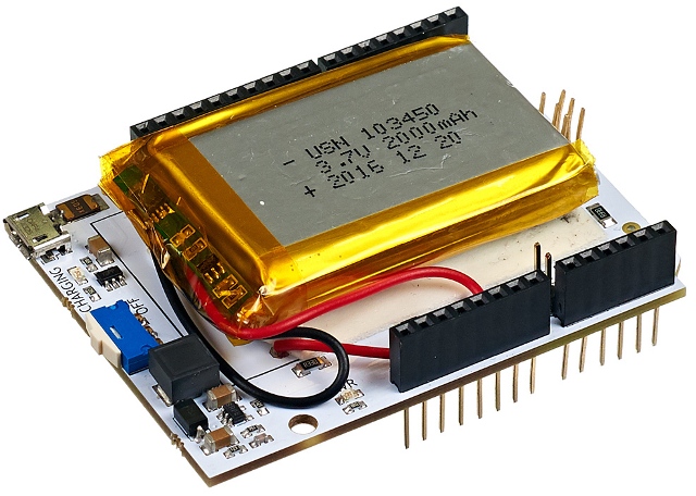
A rather unusual shield in this collection, which performs a common task. Power shield is lithium ion battery with all the necessary protections and a connector for charging. It seems to be nothing special, but it will provide a complete look to your project, and the power circuits do not have to be placed next to the main boards.
Conclusion
Using shields for all tasks of the project will allow avoiding an excessive number of jumpers and connections, and this will reduce the number of errors and extra jumpers. After assembly, you will receive a multi-story sandwich from factory-made circuit boards. This approach is sometimes called a "modular design." By the way, this will facilitate the maintenance, repair and adjustment of equipment.
Enthusiasts practice the design, wiring, and assembly of unique modules. This is one of the reasons for the high popularity of Arduino, not just as a platform for homemade products, breadboard models and prototypes, but also as a platform for turnkey solutions.
See also at e.imadeself.com
:
