Categories: Featured Articles » Novice electricians
Number of views: 34887
Comments on the article: 6
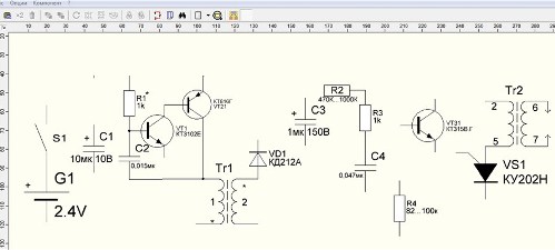
How to draw an electric lighter circuit in sPlan 7.0
 The graphic editor "Splan" is distributed free of charge, it is known among radio amateurs, electricians and electrical personnel. It is convenient in operation, has an intuitive interface and a large library of templates of electronic components, which can be replenished with your own developments.
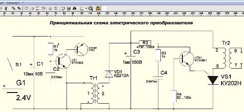
To explain the principles of drawing in the sPlan 7.0 program, we use a common electric lighter circuit, which from a voltage of 2.4 volts from two batteries generates a high-voltage spark discharge pulse to ignite the gas.
This design consists of:
-
an oscillator operating from transistors VT1 and VT21;
-
transformer Tr1, increasing their oscillations to about 150 volts;
-
high-voltage transformer Tr2;
-
triggering circuit of thyristor VS1 on transistor VT31, capacitor C4 and resistors R2, R3 and R4.
Schematic diagram of an electric lighter in sPlan 7.0 (click on the picture to enlarge):
Tr1 is wound on a ring magnetic core of ferrite 16x10x4.5 mm with 10 turns of the winding "1" and the 650th - "2". Tr2 - this is a conventional transformer from the horizontal scanning of old black and white small-sized TVs. From it, a high voltage of about 10 kV is created at the output electrodes. For safety reasons, it is better to use a factory-assembled design rather than rewinding reels at home.
Attention! When the power button is on, do not touch the electrodes. This lighter works like a stun gun, it is dangerous.
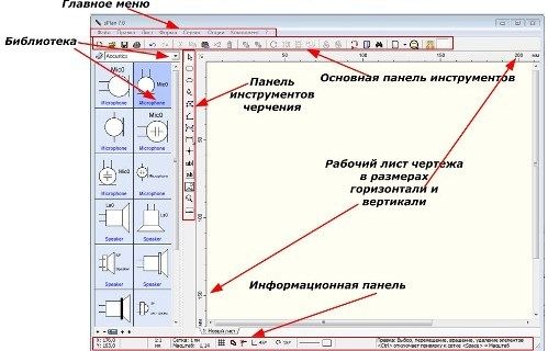
SPlan 7.0 window interface
The program is divided into blocks:
-
main menu;
-
Libraries
-
standard panel of basic and additional functions;
-
set of tools for drawing;
-
worksheet;
-
information panel.
Program window structure sPlan:
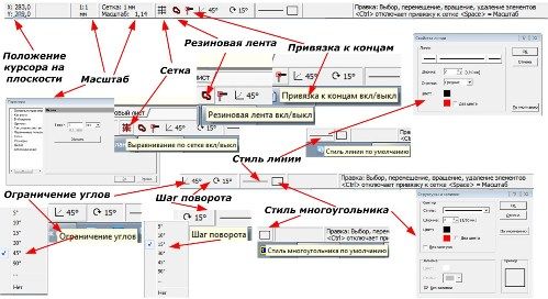
Before you start working in the program, pay attention to the information panel located at the very bottom of the window.
Information panel (click on the picture to enlarge):
Here, the position of the cursor on the workspace is indicated, the scale of the drawing is set, the grid is removed or created with the choice of its functions, angles are limited, the initial line style, polygons and the rotation step of the figures are assigned.
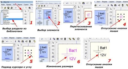
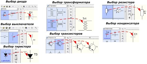
To create a drawing, select from the library all the necessary templates, transfer them to a blank sheet. The sequence of operations is shown as an example of a battery cell.
The sequence of transferring the template from the library:
In the same way, select the remaining elements:
-
transformer;
-
capacitor;
-
forward and reverse transistor;
-
thyristor;
-
diode.
Selection of element templates from the library:
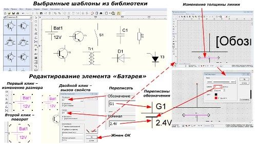
The picture below shows a general view of the selected templates in the program window and the editing sequence of one element on the example of a power supply unit of two 1.2 volt batteries connected in series to a source, which is designated "G1".
At the first left click on the template, a grid appears to change its size, and at the second - rotation. Double-clicking brings up a menu of properties that allow you to change labels, fonts, and line styles.
According to this technique, all changes are made to the selected templates, added through copying the image of transistors, transformer and resistors to the clipboard.
After editing each element, place them in the plane of the working area of the drawing.
Distribution of edited items:
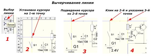
Now it remains to connect them with lines, as shown in the figure (to enlarge, click on the figure).
Left-clicking on the “Line” element with the left mouse button, we indicate the starting point with the cursor, observing the color information. Move the cursor to the next point and make another click, and then, in the same way, draw a line to the next point.At the end of the drawing, double-click and press the "ESC" button on the keyboard.
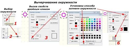
In places of electrical connections it is necessary to put points. We make them using the "Circle" element. First, select the template, and then set its size and fill.
Paste the created figure through the clipboard to all the necessary places. As a result, the drawings received a diagram of the electrical converter shown in the very first picture.
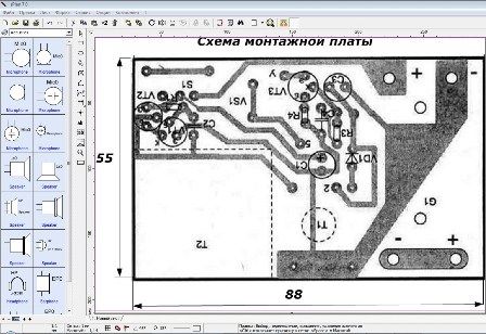
You can insert pictures in the sPlan 7.0 program field. As an example, consider a circuit board for our converter.
It will look like this:
As you can see, sPlan 7.0 works quite accurately, is easy to draw, and allows you to quickly create electrical circuits that can be printed on paper sheets or transferred to electronic media.
Drawn in sPlan 7.0 lighter circuit: https://e.imadeself.com/en/shema1.spl7
Archive with sPlan program: https://e.imadeself.com/en/splan.zip
See also at e.imadeself.com
:

