Categories: Featured Articles » Novice electricians
Number of views: 44529
Comments on the article: 7
How electricity is transmitted from power plants to consumers
Generator sets convert the energy of rivers, wind, fuel combustion, and even atomic bonds into electricity. They are distributed throughout the country, combined into a single system by transformer substations. Electricity is transferred to the distance between them by power lines. Their length can be from two to three to hundreds of kilometers.
Electricity transport lines
High-power electricity can be transmitted through power cables buried in the ground or buried in water bodies. But the most common method of transportation is via overhead lines fixed to special engineering structures - supports.
So they look for a VL-330 kV (click on the photo to enlarge):

And here is a photograph of a separate 110 kV line.

Electrical substations
Air and cable power lines connect transformer substations with the same voltage distribution devices to transfer energy from one power transformer to another.
For example, an autotransformer 330/110/10 kV receives on the high side 330 power from several lines. Electricity transmission to consumers occurs at an average of 110 and a low 10 kV part.
However, the autotransformer can be powered by medium or low voltage. It depends on the state of the circuit and the dynamics of the processes occurring in it.
Fragment Autotransformer-330kV.

View of a transformer 110/10 of a remote substation that receives electricity on side 110, distributing it along 10 kV lines.

He is, but from the opposite side.

To connect the lines to the transformers, fenced areas are used, on which the power elements of the circuit are mounted.
View of a small fragment of an open switchgear substation 330 kV.

Part of the territory of outdoor switchgear-110kV.

Variant of electric energy transmission from input 110 АТ-330 to transformer 110/10 kV
An example of a fragment of a primary power circuit (one section) of electric power distribution in an open area for 7 overhead power lines (click on the picture to enlarge):

Here, it is possible to transfer power from the inputs of 110 AT No. 1 or AT No. 2. In the circuit, each AT input was connected to its bus system with switches No. 10 and No. 15, with the tires divided into sections through switches No. 8 and No. 9 when using a bypass bus system switched by switch No. 13. Tires 1SSh and 2Sh can be combined with switch No. 18.
Overhead power lines are powered by switches No. 11, 12, 14, 16, 17, 19, 20. The circuit provides for the decommissioning of each of them to power the overhead line through the bypass bus system.
The 110 kV SF6 circuit breaker in this circuit is shown in the photo.

From it, the power is transferred to an overhead power line to a remote substation 110/10. The photo below shows its main power elements starting from the final input support of the power transmission line (click on the picture to enlarge):

Electricity is supplied to the power transformer through a disconnector, a separator, measuring current and voltage transformers.
Each of them performs certain tasks:
-
Measuring current transformers and current transformers evaluate the current and voltage vectors in the phases of the primary circuit with certain metrological errors, transfer them to the secondary protection, automation, and measurement devices for subsequent processing;
-
The disconnector is used to manually open / turn on the power circuit when there is no load on the power wires of the circuit;
-
The separator automatically disconnects the power transformer of the substation from the line to a dead time, which is created during emergency conditions in the transformer.
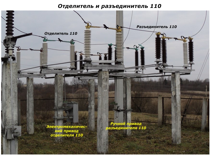
To compare the picture of the transmitted capacities and the complexity of the structures, look at the type of disconnector on the 330 kV outdoor switchgear.It is driven by powerful three-phase electric motors, controlled by automation with alarm circuits.

In a 380/220 volt network, such a device is an ordinary switch. But back to the 110/10 kV substation scheme.
Note! There is no high-voltage switch to eliminate accidents on it.
However, this does not mean that issues of safe operation have been neglected. Complicated electromagnetic transformations constantly occur in a power transformer with the release of thermal energy and the transfer of large electrical capacities. All this is controlled by measuring protection bodies.
They are located on separate panels.

In the event of critical situations, electricity is removed from the equipment from all sides: 110 and 10 kV. The supply voltage is switched off in this circuit by a gas-insulated switch located at the substation 330/110 kV.
To make it work, use the short circuit (click on the photo to enlarge):

This is a special device that serves as an executive element of the protection of a power transformer. It has a movable grounded knife with an electromechanical drive.
At a critical operating mode, the protections that monitor the state of processes inside the transformer give a powerful impulse to the electromagnet of the short-circuit coil. From it there is an impact on the latch of the spring drive, which works and imposes a short-circuit knife on high-voltage tires (the principle of the mousetrap).
An earth fault occurs in the circuit. The current from it is felt by the protection of the SF6 circuit breaker at the remote power substation. Their automation opens the circuit breaker for a certain time interval of several seconds.
During this time, at all substations connected to this power line, a dead-time pause is created. During its protection, the automation of the transformer in question issues a command to drive the separator, which automatically spreads its knives, breaking the voltage supply circuit to the power transformer, which finally “dampens the substation”.
All these operations take about 4 seconds. Upon their expiration, the automation of the remote switch makes it turn on with the voltage applied to the line. But it will not reach the damaged power transformer due to the gap created by the separator. And all other consumers will continue to receive electricity.
Reverse switching with a short-circuit and a separator is performed manually by the operating personnel after analyzing the operation of the automation according to the results of the actions of the alarm circuits.
In this way, the reliability of the equipment increases, losses during the transmission of electricity in electric networks are reduced.
10 kV circuit
From the power transformer, the converted energy of 10 kV is supplied to the input to the KRUN - outdoor complete switchgear and is distributed through a bus system and circuit breakers with protections and automation along the air or cable lines.
The 10 kV overhead power lines departing from KRUN are visible in the photo.

An overhead power line of 10 kV in the area along the highway.

Substations of 10 / 0.4 kV are connected to such lines.
Transformer 10 / 0.4 kV
The design and dimensions of power transformers that convert electricity with a voltage of 10 kV to 380 volts depend on the tasks they perform and the transmitted capacities. Their external dimensions can be estimated by several photos.

Construction in a separate enclosed building for multi-story buildings in the village.
Metal enclosed cabinets 10 / 0.4 kV in the countryside.

10 / 0.4 kV transformer in a garage cooperative (click on the photo to enlarge):

How such transformers work, energy is transferred to consumers, losses occur during the transmission of electricity in electric networks and compensation is carried out, will be described in the next article.
Continuation of the article:How electricity is transmitted to consumers through a 0.4 kV network
See also at e.imadeself.com
: