Categories: Featured Articles » Novice electricians
Number of views: 48027
Comments on the article: 1
AC Capacitors
What is alternating current?
 If we consider a direct current, then it can not always be perfectly constant: the voltage at the source output may depend on the load or on the degree of discharge of the battery or galvanic battery. Even with a constant stabilized voltage, the current in the external circuit depends on the load, which confirms Ohm's law. It turns out that this is also not quite a constant current, but such a current cannot be called variable either, since it does not change direction.
A variable is usually called a voltage or current, the direction and magnitude of which does not change under the influence of external factors, such as a load, but is completely "independent": this is how the generator generates it. In addition, these changes should be periodic, i.e. repeating over a certain period of time called a period.
If the voltage or current changes anyhow, without worrying about the frequency and other regularities, such a signal is called noise. A classic example is “snow” on a TV screen with a weak broadcast signal. Examples of some periodic electrical signals are shown in Figure 1.
For direct current, there are only two characteristics: the polarity and voltage of the source. In the case of alternating current, these two quantities are clearly not enough, so several more parameters appear: amplitude, frequency, period, phase, instant and effective value.

Picture 1.Examples of some periodic electrical signals
Most often in technology, one has to deal with sinusoidal oscillations, moreover, not only in electrical engineering. Imagine a car wheel. When driving uniformly on a good smooth road, the center of the wheel describes a straight line parallel to the road surface. At the same time, any point on the periphery of the wheel moves along a sinusoid relative to the line just mentioned.
The aforesaid can be confirmed by Figure 2, which shows a graphical method for constructing a sinusoid: whoever studied drawing well knows how to perform such constructions.

Figure 2Graphical Sine Wave Method
From the school course of physics it is known that a sinusoid is the most common and suitable for studying a periodic curve. In exactly the same way, sinusoidal oscillations are obtained in alternatorsdue to their mechanical device.
Figure 3 shows a graph of the sinusoidal current.

Figure 3Sinusoidal current graph
It is easy to see that the magnitude of the current varies over time, therefore the ordinate axis is indicated in the figure as i (t), is the function of current versus time. The full period of the current is indicated by a solid line and has a period T. If you start the consideration from the origin, you can see that at first the current increases, reaches Imax, goes through zero, decreases to –Imax, then increases and reaches zero. Next, the next period begins, as shown by the dashed line.
In the form of a mathematical formula, the current behavior is written as follows: i (t) = Imax * sin (ω * t ± φ).
Here i (t) is the instantaneous value of the current, depending on time, Imax is the amplitude value (maximum deviation from the equilibrium state), ω is the circular frequency (2 * π * f), φ is the phase angle.
The circular frequency ω is measured in radians per second, and the phase angle φ in radians or degrees. The latter makes sense only when there are two sinusoidal currents. For example, in chains with capacitor the current is ahead of the voltage by 90˚ or exactly a quarter of the period, as shown in Figure 4. If there is one sinusoidal current, then you can move it along the ordinate axis as you like, and nothing will change from this.

Figure 4 In circuits with a capacitor, the current is ahead of the voltage by a quarter of a period
The physical meaning of the circular frequency ω is what angle in radians will “run through” a sinusoid in one second.
Period - T is the time during which the sine wave will make one complete oscillation. The same applies to vibrations of a different shape, for example, rectangular or triangular. The period is measured in seconds or smaller units: milliseconds, microseconds or nanoseconds.
Another parameter of any periodic signal, including a sinusoid, is the frequency, how many oscillations the signal will do in 1 second. The unit of measurement of frequency is Hertz (Hz), named for the 19th century scientist Heinrich Hertz. So, the frequency of 1 Hz is nothing more than one oscillation / second. For example, the frequency of the lighting network is 50Hz, that is, exactly 50 sinusoidal periods pass in a second.
If the current period is known (you can measure with an oscilloscope), then the frequency of the signal will help to find out the formula: f = 1 / T. Moreover, if time is expressed in seconds, the result will be in Hertz. Conversely, T = 1 / f, frequency in Hz, time is obtained in seconds. For example, when 50 hertz the period will be 1/50 = 0.02 seconds, or 20 milliseconds. In electricity, higher frequencies are more often used: KHz - kilohertz, MHz - megahertz (thousands and millions of oscillations per second), etc.
Everything said for current is also true for alternating voltage: in Fig. 6 it is enough to simply change the letter I to U. The formula will look like this: u (t) = Umax * sin (ω * t ± φ).
These explanations are enough to return to experiment with capacitors and explain their physical meaning.
The capacitor conducts alternating current, which was shown in the diagram in Figure 3 (see article - Capacitors for AC electrical installations) The brightness of the lamp increases when an additional capacitor is connected. When the capacitors are connected in parallel, their capacitances simply add up, so it can be assumed that the capacitance Xc depends on the capacitance. In addition, it also depends on the frequency of the current, and therefore the formula looks like this: Xc = 1/2 * π * f * C.
It follows from the formula that with increasing capacitance and frequency of the alternating voltage, the reactance Xc decreases. These dependencies are shown in Figure 5.

Figure 5. The dependence of the reactance of the capacitor on the capacitance
If we substitute the frequency in Hertz into the formula and the capacitance in Farads, then the result will be in Ohms.
Will the condenser heat up?
Now recall the experience with a capacitor and an electric meter, why does it not spin? The fact is that the meter considers active energy when the consumer is a purely active load, for example, incandescent lamps, an electric kettle or an electric stove. For such consumers, the voltage and current coincide in phase, have one sign: if you multiply two negative numbers (voltage and current during the negative half-cycle), the result according to the laws of mathematics is still positive. Therefore, the capacity of such consumers is always positive, i.e. goes into the load and is released in the form of heat, as shown in Figure 6 by the dashed line.
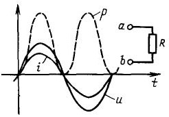
Figure 6
In the case when the capacitor is included in the alternating current circuit, the current and voltage do not coincide in phase: the current is 90 оп ahead of phase in voltage, which leads to a combination when the current and voltage have different signs.

Figure 7
At these moments, the power is negative. In other words, when the power is positive, the capacitor is charged, and when negative, the stored energy is transferred back to the source. Therefore, on average it turns out by zeros and there is simply nothing to count here.
The capacitor, unless of course it is serviceable, will not even heat up at all. Therefore, often capacitor called free resistance, which allows its use in transformerless low-power power supplies.Although such blocks are not recommended because of their danger, still it is sometimes necessary to do this.
Before installing in such a unit quenching capacitor, it should be checked by simple connection to the network: if in half an hour the condenser has not heated up, then it can be safely included in the circuit. Otherwise, you just have to throw it away without regret.
What does a voltmeter show?
In the manufacture and repair of various devices, although not very often, it is necessary to measure alternating voltages and even currents. If a sinusoid behaves so hectic, then up and down, what will a normal voltmeter show?
The average value of a periodic signal, in this case a sinusoid, is calculated as the area bounded by the abscissa axis and the graphic image of the signal divided by 2 * π radians or the period of the sinusoid. Since the upper and lower parts are absolutely identical, but have different signs, the average value of the sinusoid is zero, and it is not necessary to measure it at all, and it is even simply meaningless.
Therefore, the measuring device shows us the rms value of the voltage or current. The mean square value is such a value of the periodic current at which the same amount of heat is released on the same load as on direct current. In other words, the bulb shines with the same brightness.
This is described by the formulas like this: Icrc = 0.707 * Imax = Imax / √2 for voltage, the formula is the same, just change one letter Ucrc = 0.707 * Umax = Umax / √2. It is these values that the measuring device shows. They can be substituted into formulas when calculating according to Ohm's law or when calculating power.
But this is not all that a capacitor in an AC network is capable of. In the next article, we will consider the use of capacitors in pulsed circuits, high-pass and low-pass filters, in sine wave and square-wave generators.
Boris Aladyshkin
Continuation of the article: Capacitors in electronic circuits
See also at e.imadeself.com
: