Categories: Novice electricians, Industrial electrician
Number of views: 105522
Comments on the article: 10
How to measure grounding resistance
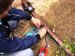 Security use of electric energy depends not only on the correct installation of the electrical installation, but also on compliance with the requirements laid down in the regulatory documentation for its operation. The grounding circuit of a building, as part of protective electrical equipment, requires periodic monitoring of its technical condition.
How does the grounding device
In normal power supply mode, ground loop PE conductor connected to the housings of all electrical appliances, the potential equalization system of the building and is inactive: through it, roughly speaking, no currents pass, except for small background ones.
How grounding protects humans
In the event of an emergency related to the breakdown of the insulation layer of the wiring, hazardous voltage appears on the body of the faulty appliance and flows through the PE conductor through the ground loop to the ground potential.
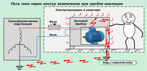
Due to this, the magnitude of the high voltage transmitted to the non-conductive parts should decrease to a safe level, which is unable to cause electrical injury to a person who is in contact with the case of faulty equipment through the ground.
When the PE conductor or ground loop is broken, there is no voltage drain path and current will pass through the human bodycaught between the potentials of a damaged appliance and the ground.
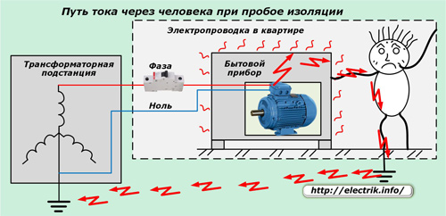
Therefore, when operating electrical equipment, it is important to maintain the ground loop in good condition and to monitor its condition with periodic electrical measurements.
How does a grounding device malfunction?
In a new serviceable circuit, the accident electric current through the PE conductor enters the collector electrodes that contact their surface with the ground and through them evenly goes to the earth potential. In this case, the main stream is evenly divided into its constituent parts.
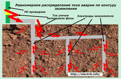
As a result of prolonged exposure to hostile soil, the metal of the current leads is coated with a surface oxide film. Incipient corrosion gradually worsens the conditions of current flow, increases the electrical resistance of the contacts of the entire structure. The rust formed on steel parts is usually general, and in some areas a pronounced local character. This is due to the uneven presence of chemically active solutions of salts, alkalis and acids that are constantly in the soil.
The resulting corrosion particles in the form of separate flakes move away from the metal and thereby stop local electrical contact. Over time, there are so many such places that the resistance of the circuit increases and the grounding device, losing electrical conductivity, becomes unable to reliably remove dangerous potential into the ground.
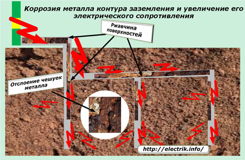
Only timely electrical measurements allow determining the moment of the critical state of the circuit.
The principles laid down in the measurement of the resistance of the grounding device
The method of assessing the technical condition of the circuit is based on the classical law of electrical engineering, identified by Georg Om for the circuit section. For this purpose, it is enough to pass a current through a controlled element from a calibrated voltage source and measure the transmitted current with a high degree of accuracy, and then calculate the resistance value.
Ammeter and Voltmeter Method
Since the circuit works in the ground with its entire contact surface, it should be evaluated when measuring. To do this, at a small distance (about 20 meters) from the monitored grounding device, electrodes are buried: the main and additional.They are supplied with current from a stabilized source of alternating voltage.
An electric current begins to flow along a circuit formed by wires, a source of EMF and electrodes with an underground conductive part of the soil, the value of which is measured by an ammeter.
A voltmeter is connected to the surface of the ground loop cleaned to pure metal and the contact of the main ground electrode.
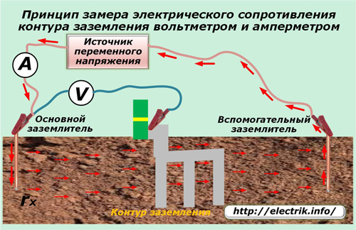
It measures the voltage drop in the area between the main earthing switch and the ground loop. Dividing the value of the voltmeter reading by the current measured by the ammeter, you can calculate the total resistance of the section of the entire circuit.
With coarse measurements, they can be limited to, and to calculate more accurate results, it will be necessary to correct the obtained value by subtracting the resistance value of the connecting conductors and the influence of the dielectric properties of the soil on the nature of the spreading currents in the soil.
Reduced by this value and measured by the first action, the total resistance will give the desired result.
The described method is quite simple and inaccurate, has certain disadvantages. Therefore, to perform better measurements made by specialists of electrical laboratories, a more advanced technology has been developed.
Compensation method
The measurement is based on the use of ready-made designs of high-precision metrological instruments manufactured by the industry.
With this method, the installation of the main and auxiliary electrodes in the soil is also used.
They are carried along a length of about 10 ÷ 20 meters and are buried on the same line, capturing the tested ground loop. A measuring probe is connected to the bus of the grounding device, trying to place the device closer to the bus contact. Connecting conductors connect the terminals of the device with electrodes installed in the ground.
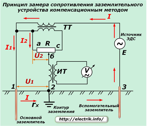
The source of the variable EMF gives a current I1 to the connected circuit, which passes through a closed circuit formed by the primary winding of the CT current transformer, connecting wires, electrode contacts and ground.
The secondary winding of the CT transformer perceives the current I2 equal to the primary one and transfers it to the resistance of the rheostat R, which allows the reochord "b" to set the balance between the voltages U1 and U2.
An isolation transformer IT translates the current I2 passing through its primary winding into its secondary circuit, which is closed to measuring device V.
The current I1 flowing along the ground in the area between the main ground electrode and the ground loop forms a voltage drop U1 in the area we measure, which is calculated by the formula:
U1 = I1 ∙ rx.
The current I2 passing through the section of the rheostat R "ab" with resistance rab forms a voltage drop U2, defined by the expression:
U2 = I2 ∙ rab.
During the measurement, move the rechord knob so that the deviation of the arrow of the instrument V is set to zero. In this case, the equality holds: U1 = U2.
Then we get: I1 ∙ rx = I2 ∙ rab.
Since the design of the device is such that I1 = I2, the relation is observed: rx = rab. It remains only to find out the resistance of the plot ab. But, for this it’s enough to make the handle of the potentiometer larger and mount an arrow on its moving part, which will move along a fixed scale, graduated in advance in the resistance units of the rheostat R.
Thus, the position of the arrow-pointer of the rheostat when compensating for voltage drops in two sections allows you to measure the resistance of the grounding device.
Using an isolation transformer IT and a special design of the measuring head V, they achieve reliable detuning of the device from stray currents. High precision measuring mechanism contributes to low impact transient resistances probe for the measurement result.
Devices operating according to the compensation method allow accurate measurement of the resistance of individual elements.To do this, it is enough to connect a conductor taken from point 1 to one end of the measured circuit, and a measuring probe (point 2) and a wire from point 3 from the auxiliary electrode to the other.
Devices for measuring the resistance of the grounding device
During the development of the energy sector, measuring instruments have been constantly improved in terms of facilitating the use and obtaining highly accurate results.
Only a few decades ago, only analogue meters of USSR production of such brands as MS-08, M4116, F4103-M1 and their modifications were widely used. They continue to work today.
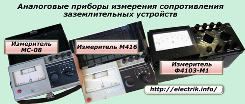
Now they are successfully supplemented by numerous devices using digital technology and microprocessor devices. They somewhat simplify the measurement process, have high accuracy, and store the results of the latest calculations in memory.

Method for measuring the resistance of the grounding device
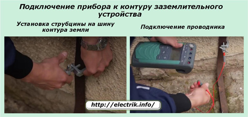
After the device is delivered to the place of measurement and removed from the transport case, the busbar is prepared to connect the contact conductor: they clean the place for connecting the crocodile clip with a file from corrosion or install a clamp with a screw clamp forcing the top layer of metal.
Three-wire resistance measurement
The requirements for safe operation require measurements to be taken when the circuit breaker is off in the building's input power panel or when the PE conductor is removed from the earthing switch. Otherwise, in the event of an emergency, the leakage current will go through the circuit and the device or the operator’s body.
The connecting conductor is connected to the device and the clamp.
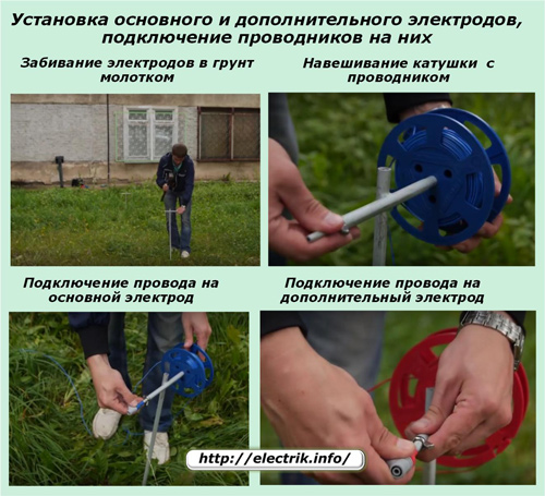
At a specified distance, ground electrodes are hammered into the ground with a hammer. Coils with connecting conductors are hung on them and their ends are connected.
Set the contacts of the wires in the socket of the device, check the readiness of the circuit for operation and the magnitude of the interference voltage between the installed electrodes. It should not exceed 24 volts. If this position is not fulfilled, then you will have to change the installation location of the electrodes and recheck this parameter.
It remains only to press the button for performing automatic measurement and remove the calculated result from the display.
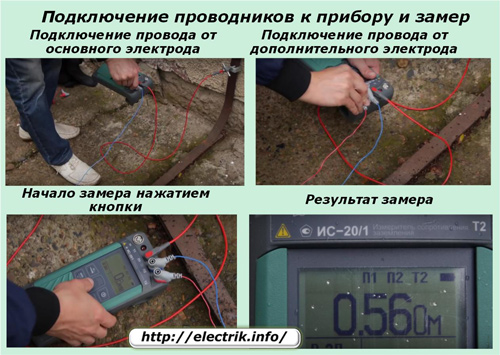
However, it is impossible to calm down after receiving the result of the first measurement. To test your work, you need to perform a small series of control measurements, rearranging the potential pin at short distances. The discrepancy of all the obtained resistance values should not diverge by more than 5%.
Four-wire resistance measurement
To use vertical electric sensing methods, ground loop resistance meters can be used in a four-wire circuit, arranging the receiving electrodes according to the Wenner or Schlumberger method.
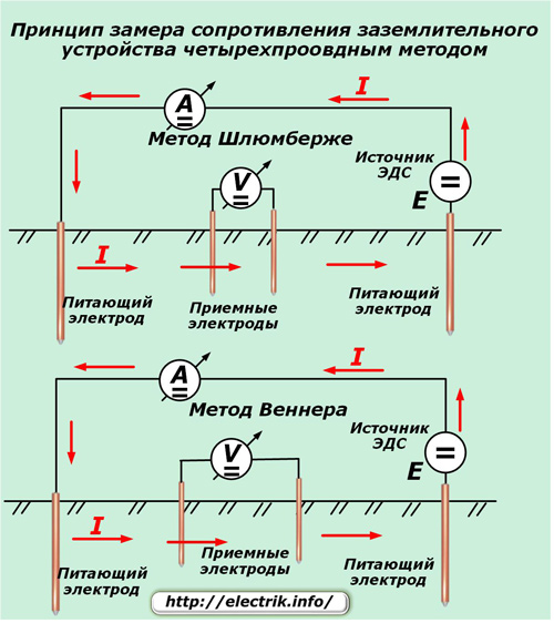
This method is more suitable for in-depth studies and the calculation of the electrical resistivity of the soil.
The connection option for the IS-20/1 device according to this scheme is shown in the picture.
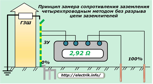
Measuring the resistance of the ground electrode using clamp meters
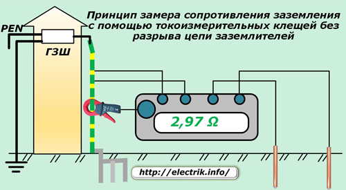
When using the method, it is necessary to have a background current from the electrical installation of the building to the ground loop. Its value in most devices operating on this type should not exceed 2.5 amperes.
Measurement of loop resistance without breaking the ground electrode circuit using measuring clamps
Using the IS-20 / 1m meter, it is possible to perform an electrical assessment of the state of the building grounding device according to the following scheme.
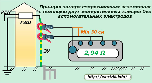
Measurement of loop resistance without auxiliary electrodes using two measuring clamps
With this method, it is not necessary to install additional electrodes in the ground, but you can perform work using two current clamp. They will need to be carried along the busbar of the grounding device to a distance of more than 30 centimeters.
The choice of measurement methodology depends on the specific operating conditions of the equipment and is determined by the laboratory specialists.
Evaluation of the condition of the grounding device can be performed at different times of the year. However, it should be borne in mind that during the period of a large presence of moisture in the soil during the autumn-spring thaw, the conditions for the spreading of currents in the ground are most favorable, and in the dry, hot weather - the worst.
Summer measurements with dried soil most qualitatively reflect the real state of the contour.
Some electricians recommend to reduce the resistance value to spill the soil near the electrodes with salt solutions. It should be understood that this measure is temporary and ineffective. With the departure of moisture, the state of conductivity worsens again, and the ions of dissolved salt will destroy the metal located in the soil.
Finally
All attentive readers and experienced electricians are invited to look at the picture below, which demonstrates a simple, at first glance, method of measuring the resistance of the grounding device, which has not found wide practical application in laboratories.
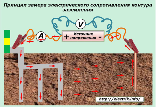
Explain in the comments what electrical processes occur with this method and how they affect the measurement accuracy. Test your knowledge, good luck!
See also at e.imadeself.com
:
