Categories: Featured Articles » Practical Electronics
Number of views: 64668
Comments on the article: 0
Feedback Operational Amplifier Circuits
Repeater and inverting amplifier
 At the end of the article “The ideal operational amplifier” It was shown that when using an operational amplifier in various switching circuits, the amplification of the cascade on a single operational amplifier (OA) depends only on the depth of feedback. Therefore, in the formulas to determine the gain of a particular circuit, the gain of the “bare” op-amp, so to speak, is not used. That is just that huge coefficient which is specified in directories.
Then it’s quite appropriate to ask the question: “If the final result (gain) does not depend on this huge“ reference ”coefficient, then what is the difference between the opamp with amplification several thousand times, and with the same opamp, but with amplification several hundred thousand and even millions? ”
The answer is quite simple. In both cases, the result will be the same, the cascade gain will be determined by the elements of the OOS, but in the second case (opamp with high gain), the circuit works more stably, more precisely, the speed of such circuits is much higher. For good reason, op amps are divided into op amps of general application and high-precision, precision.
As already mentioned, the “operational” amplifiers in question were received at that far time, when they were mainly used to perform mathematical operations in analog computers (AVMs). These were operations of addition, subtraction, multiplication, division, squaring and many other functions.
These antediluvian op-amps were performed on electron tubes, later on discrete transistors and other radio components. Naturally, the dimensions of even transistor op amps were large enough to be used in amateur constructions.
And only after, thanks to the achievements of integrated electronics, the op-amps became the size of an ordinary low-power transistor, the use of these parts in household equipment and amateur circuits became justified.
By the way, modern op-amps, even of fairly high quality, at a price slightly higher than two or three transistors. This statement applies to general purpose op amps. Precision amplifiers can cost a bit more.
Regarding the circuits on the op-amp, it’s worthwhile to immediately make a remark that they are all powered by a bipolar power source. Such a mode is the most “usual” for an op-amp, which allows amplifying not only AC voltage signals, for example, a sinusoid, but also DC signals or simply voltage.
And yet, quite often, the power supply of the circuits on the op-amp is made from a unipolar source. True, in this case, it is not possible to increase the constant voltage. But it often happens that this is simply not necessary. The circuits with unipolar power supply will be described later, but for now we continue about the schemes of switching on the op-amp with bipolar power supply.
The supply voltage of most op-amps is most often within ± 15V. But this does not mean at all that this voltage cannot be made somewhat lower (higher is not recommended). Many op-amps work very stably starting from ± 3V, and some models even ± 1.5V. Such a possibility is indicated in the technical documentation (DataSheet).
Voltage follower
It is the simplest device in terms of circuitry on an op-amp; its circuit is shown in Figure 1.

Figure 1. Voltage follower circuit on an operational amplifier
It is easy to see that to create such a scheme, not a single detail was needed, except for the OS itself. True, the figure does not show the power connection, but such an outline of the schemes is found very often. The only thing I would like to note is that between the terminals of the op-amp power supply (for example, for the KR140UD708 op-amp, these are conclusions 7 and 4) and the common wire blocking capacitors with a capacity of 0.01 ... 0.5 μF.
Their purpose is to make the operation of the op amp more stable, to get rid of the self-excitation of the circuit along the power circuits. Capacitors should be connected as close as possible to the power terminals of the chip. Sometimes one capacitor is connected based on a group of several microcircuits. The same capacitors can be seen on boards with digital microcircuits, their purpose is the same.
The gain of the repeater is equal to unity, or, to put it another way, there is no gain either. Then why such a scheme? Here it is quite appropriate to recall that there is a transistor circuit - an emitter follower, the main purpose of which is matching of cascades with different input resistances. Similar cascades (repeaters) are also called buffer.
The input resistance of the repeater on the op-amp is calculated as the product of the input impedance of the op-amp by its gain. For example, for the mentioned UD708, the input impedance is approximately 0.5 MΩ, the gain is at least 30,000, and maybe more. If you multiply these numbers, then the input impedance is 15 GΩ, which is comparable with the resistance of not very high-quality insulation, such as paper. Such a high result is unlikely to be achieved with a conventional emitter follower.
So that the descriptions are not in doubt, below are the figures showing the operation of all the circuits described in the program-simulator Multisim. Of course, all these schemes can be assembled on breadboard, but not the worst results can be obtained on the monitor screen.
Actually, it’s even a little better here: you don’t have to go somewhere on the shelf to change the resistor or microcircuit. Here everything, even measuring instruments, is in the program, and “gets” using the mouse or keyboard.
Figure 2 shows the repeater circuitry made in the Multisim program.

Figure 2
Study of the circuit is quite simple. A sinusoidal signal with a frequency of 1 KHz and an amplitude of 2 V is applied to the input of the repeater from the functional generator, as shown in Figure 3.
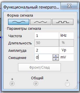
Figure 3
The signal at the input and output of the repeater is observed by the oscilloscope: the input signal is displayed by a blue beam, the output beam is red.
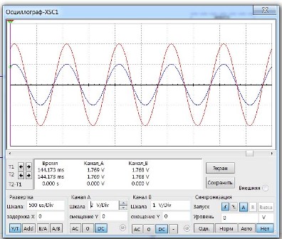
Figure 4
And why, the attentive reader will ask, is the output (red) signal twice as large as the input blue? Everything is very simple: with the same sensitivity of the oscilloscope channels, both sinusoids with the same amplitude and phase merge into one, hide behind each other.
In order to make out both of them at once, we had to reduce the sensitivity of one of the channels, in this case the input. As a result, the blue sine wave became exactly half the size on the screen, and stopped hiding behind the red one. Although to achieve such a result, you can simply shift the rays with the oscilloscope controls, leaving the sensitivity of the channels the same.
Both sinusoids are located symmetrically relative to the time axis, which indicates that the constant component of the signal is equal to zero. And what will happen if a small DC component is added to the input signal? The virtual generator allows you to shift the sine wave along the Y axis. Let's try to shift it upwards by 500mV.
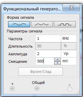
Figure 5
What came out of this is shown in Figure 6.
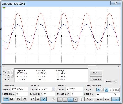
Figure 6
It is noticeable that the input and output sinusoids went up by half a volt, while not changing at all. This suggests that the repeater accurately transmitted the constant component of the signal. But most often they try to get rid of this constant component, make it equal to zero, which avoids the use of such circuit elements as interstage isolation capacitors.
The repeater is, of course, good and even beautiful: no additional details were needed (although there are repeater circuits with minor “additions”), but they did not receive any gain.What kind of amplifier is this? To get an amplifier, just add a few details, how to do this will be described later.
Inverting amplifier
In order to make an inverting amplifier from the op-amp, it is enough to add only two resistors. What came of this is shown in Figure 7.

Figure 7. Inverter amplifier circuit
The gain of such an amplifier is calculated by the formula K = - (R2 / R1). The minus sign does not mean that the amplifier turned out bad, but only that the output signal will be opposite in phase to the input. No wonder the amplifier is called inverting. Here it would be appropriate to recall the transistor included in the scheme with OE. There, too, the output signal on the collector of the transistor is in antiphase with the input signal supplied to the base.
This is where it is worth remembering how much effort you have to put in order to get a pure undistorted sinusoid on the transistor's collector. It is required to select the bias on the basis of the transistor accordingly. This, as a rule, is quite complicated, depending on many parameters.
When using an op-amp, it is enough to simply calculate the resistance of the resistors according to the formula and obtain a given gain. It turns out that setting up a circuit on an op-amp is much simpler than setting up several transistor cascades. Therefore, one should not be afraid that the scheme will not work, it will not work.
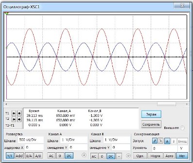
Figure 8
Here everything is the same as in the previous figures: the input signal is shown in blue, it is red after the amplifier. Everything corresponds to the formula K = - (R2 / R1). The output signal is in antiphase with the input (which corresponds to the minus sign in the formula), and the amplitude of the output signal is exactly two times the input. Which is also true with the ratio (R2 / R1) = (20/10) = 2. To make the gain, for example, 10, it is enough to increase the resistance of the resistor R2 to 100KΩ.
In fact, the circuit of an inverting amplifier can be somewhat more complicated, such an option is shown in Figure 9.

Figure 9Inverting amplifier circuit
A new part appeared here - the resistor R3 (rather, it just disappeared from the previous circuit). Its purpose is to compensate the input currents of a real opamp in order to reduce the temperature instability of the DC component at the output. The value of this resistor is selected by the formula R3 = R1 * R2 / (R1 + R2).
Modern highly stable opamps allow the non-inverting input to be connected to a common wire directly without resistor R3. Although the presence of this element will not do anything bad, but at the current scale of production, when they save on everything, they prefer not to install this resistor.
The formulas for calculating the inverting amplifier are shown in Figure 10. Why in the figure? Yes, just for clarity, in a line of text they would not look so familiar and understandable, would not be so noticeable.

Figure 10
About the gain was mentioned earlier. Here, the input and output resistances of a non-inverting amplifier are noteworthy. Everything seems to be clear with the input resistance: it turns out to be equal to the resistance of the resistor R1, but the output resistance will have to be calculated according to the formula shown in Figure 11.
The letter K ”denotes the reference coefficient of the op-amp. Here, please, calculate what the output impedance will be equal to. This will turn out to be a fairly small figure, even for an average op-amp of type UD7 with its K ”equal to no more than 30,000. In this case, this is good: after all, the lower the output resistance of the cascade (this applies not only to cascades on the op-amp), the more powerful the load, in reasonable , of course, within limits, this cascade can be connected.
A separate remark should be made about the unit in the denominator of the formula for calculating the output resistance. Suppose that the ratio R2 / R1 is, for example, 100. This is the ratio obtained in the case of the gain of the inverting amplifier 100.It turns out that if this unit is discarded, then nothing will change much. In fact this is not true.
Assume that the resistance of resistor R2 is zero, as in the case of a repeater. Then, without unity, the entire denominator becomes zero, and the output resistance is also zero. And if then this zero appears somewhere in the denominator of the formula, how do you order to divide it? Therefore, it is simply impossible to get rid of this seemingly insignificant unit.
In one article, even large enough, just do not write. Therefore, you will have everything that did not fit to tell in the next article. There will be a description of a non-inverting amplifier, a differential amplifier, a unipolar power amplifier. A description will also be given of simple circuits for checking the opamp.
Boris Aladyshkin
See also at e.imadeself.com
: