Categories: Featured Articles » Interesting Facts
Number of views: 161,925
Comments on the article: 10
Thermogenerators: how to “weld” electricity on a gas stove
 One of the electric forums asked the following question: “How can I get electricity using ordinary household gas?” This was motivated by the fact that the gas from this comrade, and indeed, like many, is paid for simply by standards without a meter.
No matter how much you use, you pay a fixed amount anyway, and why not turn already paid but unused gas into free-standing electricity? So a new topic appeared on the forum, which was picked up by the rest of the participants: an intimate conversation helps not only to reduce the working day, but also to kill free time.
Many options have been suggested. Just buy a gasoline generator, and fill it with gasoline obtained by distillation of domestic gas, or remake the generator to work immediately on gas, like a car.
Instead of an internal combustion engine, a Stirling engine, also known as an external combustion engine, was proposed. That's just the top starter (the one that created the new topic) claimed a generator power of at least 1 kilowatt, but it was rationalized, they say, such a stirling will not fit even in the kitchen of a small dining room. In addition, it is important that the generator is silent, otherwise, well, you yourself know what.
After many suggestions, someone remembered seeing a picture in a book showing a kerosene lamp with a multi-beam star device for powering a transistor receiver. But this will be discussed a little further, but for now ...
Thermogenerators. History and Theory
In order to receive electricity directly from a gas burner or other heat source, heat generators are used. Just like a thermocouple, their principle of operation is based on Seebeck effectopened in 1821.
The mentioned effect is that in a closed circuit of two dissimilar conductors an emf appears if the junctions of the conductors are at different temperatures. For example, a hot junction is in a vessel of boiling water, and the other in a cup of melting ice.
The effect arises from the fact that the energy of free electrons depends on temperature. In this case, the electrons begin to move from the conductor, where they have a higher energy in the conductor, where the energy of the charges is less. If one of the junctions is heated more than the other, then the difference in the energies of the charges on it is greater than on the cold one. Therefore, if the circuit is closed, a current arises in it, exactly the same thermopower.
Approximately the magnitude of the thermopower can be determined by a simple formula:
E = α * (T1 - T2). Here, α is the thermoelectric coefficient, which depends only on the metals of which the thermocouple or thermocouple is composed. Its value is usually expressed in microvolts per degree.
The temperature difference of the junctions in this formula (T1 - T2): T1 is the temperature of the hot junction, and T2, respectively, of the cold. The above formula is clearly illustrated in Figure 1.
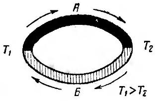
Figure 1. Thermocouple principle
This drawing is classic, it can be found in any physics textbook. The figure shows a ring made up of two conductors A and B. The junction of the conductors is called junctions. As shown in the figure, in a hot junction T1, the thermopower has a direction from metal B to metal A. A in a cold junction T2 from metal A to metal B. The direction of the thermopower indicated in the figure is valid for the case when the thermopower of metal A is positive with respect to metal B .
How to determine the thermoelectric power of a metal
The thermoelectric power of a metal is determined with respect to platinum. For this thermocouple, one of the electrodes of which is platinum (Pt), and the other is the test metal, it is heated to 100 degrees Celcius. The obtained millivolts value for some metals is shown below.Moreover, it should be noted that not only the magnitude of the thermopower changes, but also its sign with respect to platinum.
In this case, platinum plays the same role as 0 degrees on the temperature scale, and the whole scale of thermopower values is as follows:
Antimony +4.7, iron +1.6, cadmium +0.9, zinc +0.75, copper +0.74, gold +0.73, silver +0.71, tin +0.41, aluminum + 0.38, mercury 0, platinum 0.
After platinum are metals with a negative thermoelectric power:
Cobalt -1.54, nickel -1.64, constantan (an alloy of copper and nickel) -3.4, bismuth -6.5.
Using this scale it is very simple to determine the value of the thermoelectric power developed by a thermocouple composed of various metals. To do this, it is enough to calculate the algebraic difference in the values of the metals of which the thermoelectrodes are made.
For example, for an antimony-bismuth pair, this value will be +4.7 - (- 6.5) = 11.2 mV. If an iron - aluminum pair is used as electrodes, then this value will be only +1.6 - (+0.38) = 1.22 mV, which is almost ten times less than that of the first pair.
If the cold junction is maintained at a constant temperature, for example, 0 degrees, then the thermopower of the hot junction will be proportional to the temperature change, which is used in thermocouples.
How thermogenerators were created
Already in the mid-19th century, numerous attempts were made to create heat generators - devices for generating electrical energy, that is, for powering various consumers. As such sources, it was supposed to use batteries from series-connected thermocouples. The design of such a battery is shown in Figure 2.
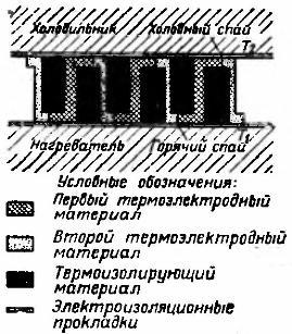
Figure 2. Thermal battery, schematic
The first thermoelectric battery created in the mid-19th century by physicists Oersted and Fourier. Bismuth and antimony were used as thermoelectrodes, just the same pair of pure metals with the maximum thermoelectric power. Hot junctions were heated by gas burners, and cold junctions were placed in a vessel with ice.
In experiments with thermoelectricity, thermopiles were later invented, suitable for use in some technological processes and even for lighting. An example is the Clamone battery, developed in 1874, whose power was quite enough for practical purposes: for example, for galvanic gilding, as well as for use in printing houses and helio-engraving workshops. Around the same time, the scientist Noé was also involved in the study of thermopiles; his thermopiles were also quite widespread at the time.
But all these experiments, although successful, were doomed to failure, since thermopiles based on pure metal thermocouples had a very low efficiency, which hampered their practical application. Purely metallic fumes have an efficiency of only a few tenths of a percent. Semiconductor materials possess much greater efficiency: some oxides, sulfides, and intermetallic compounds.
Semiconductor Thermocouples
A true revolution in the creation of thermocouples was made by the works of Academician A.I. Joffe. In the early 30s of the XX century, he put forward the idea that using semiconductors it is possible to convert thermal energy, including solar, into electrical energy. Thanks to the research already in 1940, a semiconductor photocell was created to convert solar light energy into electrical energy.
First practical application semiconductor thermocouples it should be considered, apparently, a “partisan bowler”, which made it possible to provide power to some portable partisan radio stations.
The basis of the thermogenerator was elements from constantan and SbZn. The temperature of the cold junctions was stabilized by boiling water, while the hot junctions were heated by the flame of a fire, while a temperature difference of at least 250 ... 300 degrees was ensured. The efficiency of such a device was no more than 1.5 ... 2.0%, but the power to power the radio stations was quite enough.Of course, in those wartime times, the design of the "bowler" was a state secret, and even now, its design is being discussed on many Internet forums.
Household heat generators
Already in the post-war fifties, Soviet industry began production thermal generators TGK - 3. Its main purpose was to power battery-powered radios in non-electrified rural areas. The generator power was 3 W, which made it possible to power battery receivers, such as Tula, Iskra, Tallinn B-2, Rodina-47, Rodina-52, and some others.
The appearance of the TGK-3 thermogenerator is shown in Figure 3.
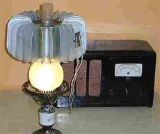
Figure 3. Thermal generator TGK-3
Thermal Generator Design
As already mentioned, the heat generator was intended for use in rural areas, where lighting was used kerosene lamps "lightning". Such a lamp, equipped with a thermal generator, became not only a source of light, but also electricity.
At the same time, additional fuel costs were not required, because exactly that part of kerosene that simply flew into the pipe turned into electricity. Moreover, such a generator was always ready for operation, its design was such that there was simply nothing to break into it. The generator could simply lie idle, work without load, was not afraid of short circuits. The life of the generator, compared to galvanic batteries, seemed simply eternal.
The role of the exhaust pipe of the kerosene lamp “lightning” is played by the elongated cylindrical part of the glass. When using the lamp together with the heat generator, the glass was shortened and a metal heat transfer unit 1 was inserted into it, as shown in Figure 4.
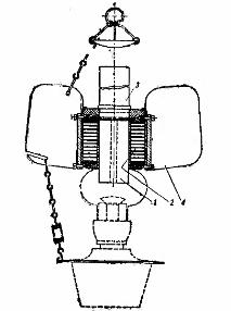
Figure 4. Kerosene lamp with thermoelectric generator
The external part of the heat transmitter is in the form of a multifaceted prism on which thermopiles are mounted. To increase the efficiency of heat transfer, the heat transmitter inside had several longitudinal channels. Passing through these channels, the hot gases went into the exhaust pipe 3, simultaneously heating the thermopile, more precisely, its hot junctions.
An air-cooled radiator was used to cool the cold junctions. It is a metal rib attached to the outer surfaces of thermopile blocks.
Thermogenerator - TGK3 consisted of two independent sections. One of them generated a voltage of 2V at a load current of up to 2A. This section was used to obtain the anode voltage of the lamps using a vibration transducer. Another section with a voltage of 1.2 V and a load current of 0.5 A was used to power the filament of the lamps.
It is easy to calculate that the power of this heat generator did not exceed 5 watts, but it was enough for the receiver, which made it possible to brighten up long winter evenings. Now, of course, this seems just ridiculous, but in those days, such a device was undoubtedly a miracle of technology.
In 1834, the Frenchman Jean Charles Atanaz Peltier discovered the effect opposite to the Seebick effect. The meaning of the discovery is that during the passage of current through the junction from dissimilar materials (metals, alloys, semiconductors) heat is released or absorbed, which depends on the direction of the current and types of materials. This is described in detail here: Peltier effect: the magic effect of electric current
See also at e.imadeself.com
:
