Categories: Electrician at home, Safety precautions
Number of views: 51473
Comments on the article: 10
Electrosafe private residential building and cottage. Part 2
Begin the article here - Electrosafe private residential building and cottage. Part 1.
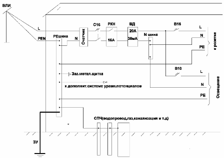
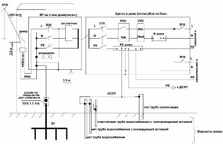
 System TN - C - S. In the final version, we have the following scheme - see. fig. 11 and fig. 12. The diagram shows the minimum necessary kit to protect your home. The ILV relay will protect your home from overvoltage and undervoltage at the input. And if you can’t protect yourself from the increased voltage (breaking the PEN wire is unlikely), but what the hell doesn’t joke, and the lower voltage can always take place, which is extremely dangerous for electric motors. In addition, if you have an UZO electronic, then with a reduced voltage or a broken only neutral wire, it may simply not work and leave the house without protection.
The RCD will protect you from direct contact with the phase wire, from leakage currents that can cause a fire, and also instantly turn off the faulty power plant (when the phase closes to its case). The circuit breaker will monitor short-circuit currents and overload in the network.
Regarding the re-grounding of the PEN wire ....
According to the PUE, clause 1.7.61 "... Re-grounding of electrical installations with voltages up to 1 kV, powered by overhead lines, MUST be performed in accordance with clause 1.7.102-1.7.103." According to p.1.7.102 "... and also on the overhead line inputs to electrical installations in which automatic power off is used as a protective measure for indirect contact, repeated grounding of the PEN conductor MUST be performed."
Thus, the PUE obliges us to re-ground the PEN - wires at the entrance to the house with the TN-C-S system. According to paragraph 1.7.103, the resistance of re-grounding in our case should be no more than 30th. Keep in mind that this resistance is measured when the PEN wire is disconnected (that is, without taking into account all the repeated grounding external to your house - repeated grounding on the overhead line). If you then connect the PEN wire from the overhead line again to your repeated grounding, then the total resistance should be no more than 10 Ohms (see clause 1.7.103).
Since we cannot be sure that all re-groundings are made on the overhead line, it may turn out that our re-grounding is the only one on the overhead line, that is, it must be less than 10 Ohms. Therefore, it is necessary to immediately focus on the value of not more than 10 Ohms in ordinary soil (in sandy, not more than 50 ohms) when installing your grounding device. Representatives of gas companies also require this, if you have a gas boiler.
Fig. 11. System TN-C-S (click on the picture to enlarge)
Fig. 12. System TN-C-S according to PUE 7.1.22 (click on the picture to enlarge)
Now let's deal with the choice of circuit breakers.
First you need to understand that the circuit breaker that protects your sockets should not be higher than 16A, and the one that protects the lamps should not be higher than 10A. Why? The fact is that all the electrical appliances that you use in the house are connected to sockets with a cord, and this cord, according to the norms, should not be a cross section of less than 0.75 sq. Mm in copper. The rated current for this section is 16A.
If you set the circuit breaker to 25A, then it will start to "do something" only at a current of more than 25A and if 25A current flows through the cord rated for 16A, this will cause it to heat up, melt the insulation and ultimately to the current Short circuit in the cord and the fire in the house. Similarly with luminaires, as according to the norms, all internal connections in them must be made with a copper wire with a cross section of at least 0.5 sq. Mm. For such a cross section, the rated current is 10A.
Well, remember. The circuit breaker no more than 16A protects sockets, and at 10A - lamps. Move on. It must be remembered that circuit breakers are of type B, C, D. We are only interested in type B and C. What is it?
Type B is a circuit breaker that disables the electrical installation within 3 -5 1nom. Accordingly, type C is within 5-10 1nom. For what specific time the machine will work, look at its protective characteristics. But we are not designers, so we’ll do it easier and better in terms of electrical safety.
According to GOST, according to which all these machines are manufactured, its response time at the upper limit (for type B is 5 Inom, and for type C it’s 10 Inom) must be no more than 0.1 sec. And according to table 1.7.1 of the PUE, the time for switching off the machine at 220V should be no more than 0.4 sec. What is it for? Scientific studies have found that the severity of electric shock affects both the magnitude of the voltage and the time during which it acts on the person. If a person, for example, touched open conductive parts (HRE), on which the phase (220V) suddenly “sat down”, then it is believed that a person should not be energized for more than 0.4 sec (for 220V), that is, it will be for him safely. Remember - I wrote above that I will tell you how to get rid of the stress of touch - this is exactly the way.
So, we will not consider the protective characteristics of machines. The fact that a type B machine with a short-circuit current of 5 Inom. (A machine of type C for 10 1nom.) instantly (for 0.1sec) disconnect the voltage, we are quite happy. We will focus on this.
Move on. It turns out that for the instantaneous operation of an automatic machine of type B at 16 amperes, a current equal to 5x16 = 80 A is needed, and for type C a current of 10x16 = 160 A is needed. And what section of wires is needed to guarantee such a current? Let's count a little.
R = U / 1 = 220/80 = 2.8 Ohms
S = 0.0175xL / S sq. Mm
Suppose, for example, this machine protects the wiring to an outlet installed at a distance of 100 meters. Then S = 1.25 sq. Mm. According to the PUE, the minimum cross-section of copper wires should be at least 1.5 sq. Mm according to the conditions of mechanical strength. Therefore, making the wiring to our outlet a copper wire with a cross-section of 1.5 sq. Mm, we will fulfill the requirements of the PUE and reliably protect everything that is in the protection zone of this machine.
Now take a 16 A machine, but type C, and do similar calculations. We see that in the case of a type B machine, the wiring to the outlet is at a distance of 100 m can be made a wire with a cross-section of 1.5 square mm, and for a type C machine, a wire with a cross-section of 2.5 sq. mm in copper. What is best for your home - I think you can figure it out yourself. The main thing is that you already understand the essence of the problem.
Now let's talk about choosing an RCD.
As a rule, we are not rich people and buy UZO so-called "electronic", that is, if power is supplied to it (in this case, from the 220V network itself), then it works and protects our house and person. And if, for example, there is a break in the neutral wire to the RCD itself, then the phase will go into the house, and the RCD will be inoperative with all the ensuing consequences. Therefore, I highly recommend installing an ILV relay that will track this and other troubles. If possible, instead of a combined RCD (RCD plus an automatic machine in one housing), it is better to choose a separate RCD and an automatic machine, since when a combined RCD is tripped, it is impossible to understand why it worked - from overload, short-circuit current, leakage current, phase closure to the HRE or HFC housing. With a separate machine and RCD - everything becomes immediately clear. RCD at rated current should be selected one step above the machine that stands in front of it
Since we are considering an ordinary residential building, and not a huge mansion, then the RCD at the entrance to the house must be taken at 20 or more amperes and a differential current of 30 Ma, that’s enough to protect your home. It is better to take an input circuit breaker than one-pole, but two-pole for the TT system and three-pole for the system TN-C-S (PUE 1.7.145).
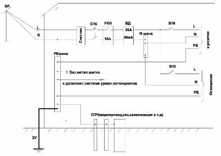
Fig. 13. TT system (click on the picture to enlarge)
If you carefully read everything written above, then you can easily figure out the TT system as well. Its differences from the TN-C-S system are that the PEN wire is not separated at the input to PE and N conductors.The PEN conductor now plays the role of only the N conductor (working zero) and therefore is immediately connected to the electric meter.
We must do the PE conductor ourselves by performing the EARTHING DEVICE on the site and connecting the RE-bus of the input shield to it. From this backplane bus we will take PE conductors to sockets and where necessary, as in the TN-C-S system. But in the TT system there is one problem - it is impossible to create large currents for the operation of automatic machines in it. It is one thing to close the phase and neutral wires between each other, and it is quite another to stick the phase into the ground. Even if we make a grounding device with a resistance of 10 ohms, we get a current of 220/10 = 22 A - a meager current for the operation of the machines, so that they are now no help to us. What to do?
Here the UZO at 30mA (0.03A) comes to the rescue. Such an RCD will work with a current to earth of only 0.03A, that is, just what we need. The requirements for grounding resistance in the TT system are less stringent than in the TN-C-S system. What does it mean less stringent? Let's figure it out.
According to PUE 1.7.59 in the TT system, the grounding resistance should be R s <50 / Id-R zp, where 50 is the largest contact voltage on the HRE and the HF Id -dif. RCD current R zp is the resistance of the grounding conductor Since the distances in our residential building are small, we can take Rzp = 0 Then R z <50 / Id
In a private house there are a lot of especially dangerous places - a street, sheds and so on, therefore we will not save on electrical safety and will accept instead of 50 volts 12 volts. From 12 volts certainly will not kill. Then Rz = 12 / 1.4xId = 12 / 1.4x0.03 = 286 Ohms, that is, the ground resistance should be at least 286 Ohms.
The draft new revision of the MES 60364-4-41 standard sets the maximum values for the response time of automatic power off in the TT system. This is 0.2 seconds at 120-230 volts and 0.07 seconds at a voltage of 230-400 volts. RCDs of type A and AC are triggered during the indicated time when sinusoidal earth fault currents appear (1z) Iz = 2 Id (for voltage 120-230) Iz = 5 Id (for voltage 230-400 volts).
With pulsating earth fault currents, a Type A RCD trips for the indicated time when the fault current is equal to: Iz = 1.4x2 Id (at a voltage of 120-230 volts) Iz = 1.4x5 Id (at a voltage of 230-400 volts). The maximum resistance value under the most adverse conditions will be: 12 / 1.4x5x0.03 = 57 Ohms. This is the resistance of the grounding device and you need to navigate. However, according to circular No. 31.2012 “On the implementation of re-grounding and automatic power off at the input of individual construction objects”, the resistance of re-grounding should be no more than 30 Ohms. With a specific soil resistance of more than 300 Ohm x m, an increase in resistance of up to 150 Ohm is allowed.
Entrance to the building power supply
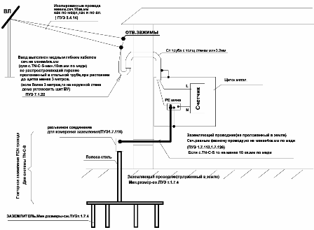
Now let's dwell in more detail on how to correctly perform input from the overhead line to the house. Most residential buildings do not require a load current of more than 25 A (this is approximately 10 kW of power). Then we turn directly to clause 7.1.22 of the PUE, which indicates in detail how to enter in this case. All the requirements of this paragraph (and of course other PUE standards) I have depicted in Fig. 14.
Fig. 14. Input from overhead lines with rated current up to 25 A. According to PUE 7.1.22. (click on the picture to enlarge)
All the necessary explanations are given directly in the figure, so I will point out the most common errors with the input device. The most dangerous mistake is not to protect the wiring with the pipe to the shield itself. This is not done all the time, and therefore any short circuit in this section of the wiring, which also has no protection, leads to spraying of hot metal, and the fire in the house is almost guaranteed. And even if the wiring is made in a pipe, then not every pipe will pass such a test. Therefore, the metal pipe should be with a wall thickness of at least 3.2 mm (for our case).
Another, but not so obvious mistake - this is very often done by SIP input directly into the house to the shield, without cutting it at the insulators. Of course, this method has its advantages, but if the input wires to the house are not made of COPPER, NOT FLEXIBLE, not INSULATED wire, in NON-COMBUSIBLE INSULATION, not with LIGHT-stabilized properties, then we do not fulfill the requirements of the PUE. What can I say?
In this example, the branch and entry into the house are performed by SIP sec. 16 sq. Mm. With such a cross-section and a load in the house with a current of less than 25 A, the copper wire or aluminum is hardly significant. The fact that SIP is flexible does not seem to be in doubt either, and even with such a cross section.The fact that SIP 4 is made with insulation with light stabilized properties \, the same is clear. There is only one indicator that remains - insulation must be non-combustible, and this is the most serious argument. Even if you protect the wiring with a pipe, this is not a way out, since the fire is very insidious.
Now SIP5 ng has appeared on sale - that is, in non-combustible isolation. Then we can talk about direct entry of self-supporting insulated wires into the house, though we still formally violate the PUE. The conclusion from all this is obvious - there is no need to take risks, everything must be done according to the rules of the PUE. And if you prefer SIP, then do its cutting at the entrance to the house, and then enter the house itself and make a COPPER FLEXIBLE CABLE section. not less than 4 sq. mm in NON-combustible insulation with light-stabilized properties and laid up to the shield in met. pipe with a wall thickness of at least 3.2 mm.
In the end, we consider what dangers can be expected from the OHL itself.
Fig. 15. Emergency situations on overhead lines
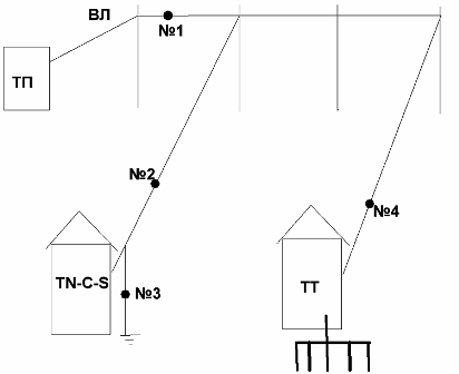
Fig. 15 shows a transformer substation (TP) from which the trunk line of the overhead line goes and from it branches are made to enter the house. In one house s.TN-C-S is made and in another s.T.T. Possible emergency situations on the overhead line are numbered 1-4. Emergency No. 1 - common to both houses - is a break in the PEN wire on the overhead line. Emergency # 2 is a break in the PEN wire on the branch to the house (that is, from the pole to the house). Emergency number 3 - failure to re-ground the PEN wire at the entrance to the house. Emergency No. 4 - a zero wire break on a branch to the house.
If we analyze emergency situations No. 1-4, provided that we MANDATORYly installed a circuit breaker, an RCD and an ILV relay, then: In case of emergency No. 1 in the TN-C-S system, a high potential is possible with a failure of re-grounding on the HRE electrical equipment. There is no such danger in the TT system. In case of emergency No. 2, the TN-C-S system does not have short circuit protection in the wiring. There is such protection in the TT system. In case of accidents No. 3 and No. 4, the house with the TN-C-S system and the house with the TT system are equally protected. From all this we can conclude that the TT system is the safest.
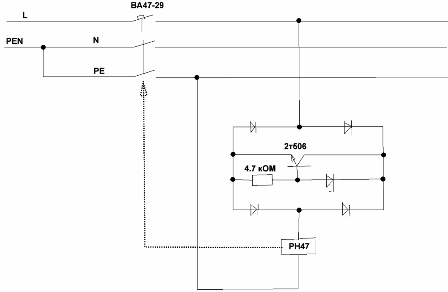
At the end of the article I want to offer in the discussion order. You probably noticed that in private residential buildings PUE 1.7.145 allows you to simultaneously break PE, L and N wires. Of course, I took advantage of this right and reflected it in the figure. It is clear and why this is necessary. It is very good if the machine itself automatically disconnected all the wires at the input, when the voltage on the PE wire would rise, for example, to 60 volts.
Further in the figure I give a diagram that allows this to be implemented. The diagram shows a 3-pole circuit breaker, for example, BA47-29 and a PH47 relay. The machine is installed on the dinreake and next to it is installed on the side of the relay, which is mechanically interlocked with the machine. If you now apply a voltage of 230 volts to the relay, then it will work and turn off the machine. Next, I write everything approximately, since the scheme needs to be brought to mind.
We reason like this. Assume that the relay operates at a voltage of 0.8x230 = 180 volts (it can be precisely specified during the experiment). When the voltage on the PE wire rises, for example, up to 60 volts, between the L wire and the PE wire will be 220 + 60 = 280 volts. Then 280-180 = 100 volts, this means that 220-100 = 120 volts <180 volts and the relay will not work, and 280-100 = 180 volts = 180 volts and the relay will work.
In the diagonal of the bridge, turn on the transistor. When the voltage at the zener diode is 100 volts (we select a zener diode at 100 volts), the transistor will open and the relay will trip. The machine will turn off and break the L, PE and N conductors and at the same time the power circuit of the relay itself will break.
Continuation of the article: Electrosafe private residential building and cottage. Part 3. Lightning protection
See also at e.imadeself.com
:

