Categories: Home automation, Programmable controllers
Number of views: 47972
Comments on the article: 7
Using ARIES PLC in automatic lighting control systems
 Home automation often starts with the simple, urgent task of controlling lighting. It is often necessary to control the on and off light from different places or from a common remote control or a set of buttons. Moreover, the number of lighting fixtures, rooms, switches is always different. And the control scheme is different from task to task.
In this material we will consider a universal means of solving this problem - freely programmable Aries PLC controller.
With this device, you can automate the lighting of almost any complexity. At the same time, intermediate contacts are not needed, switching of electric circuits occurs using built-in electromagnetic relays.
The creation of the work algorithm begins with loading CoDeSys programs. It is free and is included with the PLC.
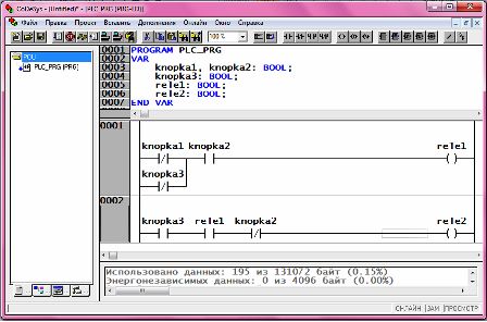
CoDeSys implements several methods (languages) for developing an algorithm. One of the most obvious is LD relay circuits.

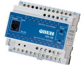
Programmable controller Aries PLC
Suppose that you need to solve the standard task of implementing a pass-through switch. Whichever way you enter the room, you turn on the light. Whichever way you go, the light turns off. For two switches, the task is solved by conventional contacts. But with an implementation with three or more switches, things get a little more complicated.
In the LD language, it is customary to implement discrete (relay) algorithms. The circuit collects series-connected and parallel-connected contacts. Their order and placement define certain logical functions. A serial connection defines the logic “AND”, parallel - “OR”. In addition, there are normally closed and normally open contacts.
Each contact is associated with a variable. This may be an input to the controller, such as a switch. It may be an intermediate variable. The result of the algorithm, a variable associated with the output relays, is set in the form of a winding. This element is always placed at the end of the chain, on the right. When the signal passes through the winding in the LD circuit, the PLC physical output relay closes. When in the program the signal stops passing through the winding, the relay opens.
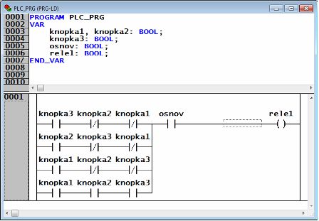
An example of the implementation of a passage switch for three buttons and a common toggle switch is shown in the figure.
We see four chains. Each of them estimates the current position of the three switches. If any one switch goes into the on state, the signal passes through the rele1 winding. If all switches are on, rele1 is also on. In all other cases, the signal transmission condition is not satisfied, and rele1 is disabled.
You can check the operation of this circuit directly in the programming system. You do not need to have a PLC for this. CoDeSys implements a controller emulation system. Thus, you can study programming and try your first algorithms right on your computer.
For more information, see the video course, "Developing Process Control Systems in Codesys." The video course is designed specifically for beginners with no programming experience. It provides step-by-step instructions for creating the first projects in CoDeSys, so that you can immediately begin to develop your own algorithms.
Watch PLC programming tutorials in CoDeSyscan be here:PLC Programming Lessons
We tried to make the description as simple and understandable as possible for any technically competent person.
If the information in this article seemed useful to you, write to the author what other simple examples of home automation you would be interested to make out.
See also on our website:
Ladder Diagram (LD) Programming Language
The principles of programming programmable controllers in the FBD language
See also at e.imadeself.com
:


