Categories: Featured Articles » Home automation
Number of views: 39628
Comments on the article: 0
What is a PID controller?
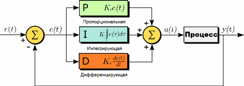
PID (from the English P-proportional, I-integral, D-derivative) - a regulator is a device used in control loops equipped with a feedback link. These controllers are used to generate a control signal in automatic systems where it is necessary to achieve high requirements for the quality and accuracy of transients.
The control signal of the PID controller is obtained by adding three components: the first is proportional to the value of the error signal, the second is the integral of the error signal, and the third is its derivative. If any of these three components is not included in the addition process, then the controller will no longer be PID, but simply proportional, proportionally differentiating or proportionally integrating.
The first component is proportional
The output signal gives a proportional component. This signal leads to counteraction to the current deviation of the input quantity to be regulated from the set value. The larger the deviation, the greater the signal. When the value of the controlled variable is equal to the set value at the input, the output signal becomes equal to zero.
If we leave only this proportional component, and use only it, then the value of the quantity to be regulated will never stabilize at the correct value. There is always a static error equal to such a value of the deviation of the controlled variable that the output signal stabilizes at this value.
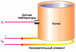
For example, a temperature controller controls the power of a heating device. The output signal decreases as the desired object temperature approaches, and the control signal stabilizes the power at the level of heat loss. As a result, the set value will not reach the set value, because the heating device in just has to be turned off, and starts to cool (power is zero).

The gain between the input and output is greater - the static error is less, but if the gain (in fact, the proportionality coefficient) is too large, then subject to delays in the system (and they are often inevitable), self-oscillations will soon begin in it, and if you increase the coefficient is even greater - the system will simply lose stability.
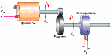
Or an example of positioning a motor with a gearbox. With a small coefficient, the desired position of the working body is reached too slowly. Increase the coefficient - the reaction will be faster. But if you increase the coefficient further, the engine will “fly over” the correct position, and the system will not quickly move to the desired position, as one would expect. If we now increase the proportionality coefficient further, then oscillations will begin near the desired point - the result will not be achieved again ...

The second component is integrating
The time integral of the mismatch is the main part of the integrating component. It is proportional to this integral. The integrating component is used just to eliminate the static error, since the controller over time takes into account the static error.
In the absence of external disturbances, after some time, the value to be regulated will be stabilized at the correct value when the proportional component turns out to be zero, and the output accuracy will be entirely ensured by the integrating component. But the integrating component can also generate oscillations near the positioning point, if the coefficient is not selected correctly.
The third component is differentiating
The rate of change of the deviation of the quantity to be regulated is proportional to the third, the differentiating component.It is necessary in order to counteract deviations (caused by external influences or delays) from the correct position, predicted in the future.
PID Controller Theory
As you already understood, PID controllers are used to maintain a given value x0 of some one quantity, due to a change in the value of u of another quantity. There is a setpoint or a given value x0, and there is a difference or discrepancy (mismatch) e = x0-x. If the system is linear and stationary (practically this is hardly possible), then for the definition of u the following formulas are valid:

In this formula, you see the proportionality coefficients for each of the three terms.
In practice, PID controllers use a different formula for tuning, where the gain is applied immediately to all components:

The practical side of PID control
Practically theoretical analysis of PID-controlled systems is rarely used. The difficulty is that the characteristics of the control object are unknown, and the system is almost always unsteady and non-linear.
Actually working PID controllers always have a limitation of the operating range from below and above, this fundamentally explains their non-linearity. Therefore, tuning is almost always and everywhere done experimentally when the control object is connected to the control system.
Using the value generated by the software control algorithm has a number of specific nuances. If we are talking, for example, about temperature control, then often it is still necessary not just one, but two devices at once: the first controls heating, the second controls cooling. The first delivers the heated coolant, the second - the refrigerant. Three options for practical solutions can be considered.
The first is close to the theoretical description when the output is an analog and continuous quantity. The second is an output in the form of a set of pulses, for example, for controlling a stepper motor. Third - PWM controlwhen the output from the regulator serves to set the pulse width.

Today, almost all automation systems are under construction based on PLC, and PID controllers are special modules that are added to the control controller or generally implemented programmatically by loading libraries. To properly set the gain in such controllers, their developers provide special software.
See also at e.imadeself.com
:

